|
Title: |
1894 Article-Henry C. Ayer & Gleason Co., Machine for Turning Irregular Forms |
|
Source: |
Industry Magazine, Sep 1894, pg. 524 |
|
Insert Date: |
12/8/2012 1:03:41 PM |
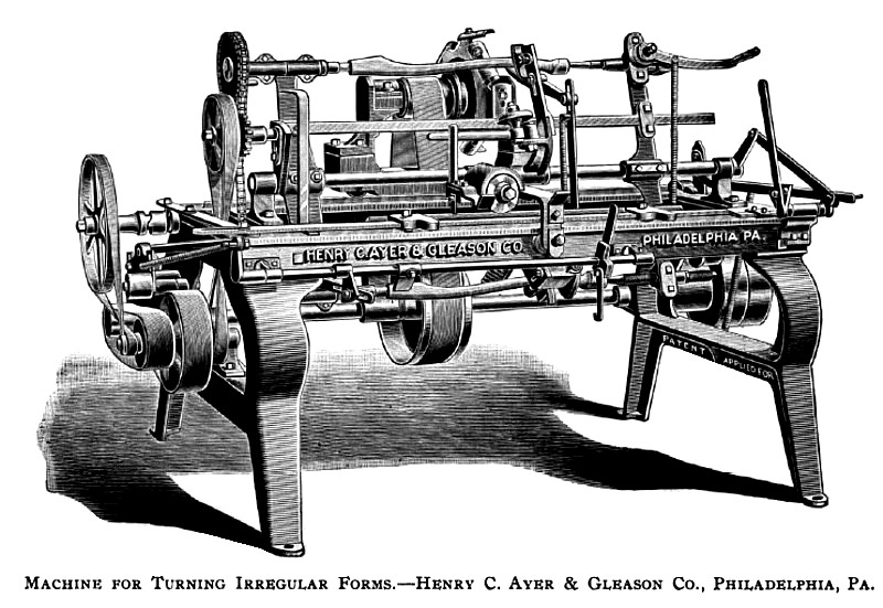
The machine shown opposite, which is sometimes called a duplicating one, or spoke and handle lathe, is, in its various types, one of the most remarkable ever invented in this country, and one that has had a great deal to do in developing woodworking industry of various kinds.
The principle product, as one of the names above given implies, is spokes and handles, and these alone are an enormous item, but there are many other things shaped in this way. We remember once happening in a shop where hobby horses were being turned out of blocks of tulip wood on one of these machines. Shoe lasts are turned on machines but little modified from the above, the main difference being that the lasts are quite expensive in comparison with spokes and handles, consequently can be turned slower and smoother.
Before speaking of the particular machine shown in the drawing, and one that has the first important change made for thirty years past, we will treat this subject of turning or "machining" irregular forms in a general way. It is one that has always been of popular interest, because the common ideas of machine action are associated with regular forms, bounded by right lines or true curves, square or round, and this does comprehend the greater part that is done on machines, still, as before said, irregular forms hold a prominent place. The original conception of working from models, or duplicating with cutters guided by a model, on the principle of a pantograph, was invented in France. Under what circumstances, and by whom, we cannot say, but of the fact there is no doubt, as will appear farther on.
The first application of which we have any account in our own language dates from the beginning of the century, and with the most noted engineer and mechanic of that time, James Watt, who about the year 1812 began the construction of machines of this kind, or for duplicating. It was after he and Boulton had brought the steam engine up to its successful form, and the revenue from sales and royalties was sufficient to relieve Watt in a measure from his labors at the Soho Works.
Watt's home was at Heathfield, about two miles from Soho, where he had nineteen acres of ground, a native forest, and near the center a quaint rambling old English house, yet standing, but extended by its present owner in 1886. In one wing he set up a workshop over the kitchen, where he spent a great shafe of his time from the date above given down to 1819, when he died. The old house is now leased and occupied by George Tangye, Esq., managing partner in the Great Cornwall Iron Works of Tangye Bros., near Soho, and near the old Boulton & Watt Works, now represented by James Watt & Co.
The most prominent thing to be seen in this old workshop of Watt's, which we examined some years ago, were these duplicating machines. On one of them was a medallion half finished, and just as James Watt left it in 1819. Nothing has been disturbed since then, even the embers in the stove lie as left seventy-four years ago, while nearly central in the floor stands the copying machine. It is a pantograph-carving machine, if we give it a technical name, but it has all the elements of this class of machines, and is even a most advanced type. Our readers will wonder why Watt did not give this matter more publicity, or secure patents on his invention. There are two reasons. He learned before his death that his invention had been anticipated in France, and he died before he had completed his machines for carrying the scheme into practical effect. This is the beginning of the art in England, but it did not pass into public use.
In this country the first machines of the kind were invented in 1820 by Boyd or Blanchard, and, as we believe, with the object of turning or shaping musket stocks for the United States Armory at Springfield, Mass. This invention, which was a thoroughly practical one, was made quite independent of the pantograph methods in England or in France, and with the difference that the movements required to follow the form were given to the pieces to be shaped or' cut, and the cutters were stationary or mounted on fixed spindles parallel to the axis of the work and the model. This, while it would not produce all kinds of irregular forms, met the principal requirements in various manufactures, and permitted the use of large cutters mounted on heads of large diameter, as seen in the drawing.
The amount of cutting done by any wood cutting implement is commonly as the length of the cutting edges multiplied into their velocity. In the Blanchard type, or in the machine in the drawing, six or more cutters can be used aggregating a length or width of edge up to two feet, or more if required, while in the pantograph type one inch of cutting edge would be a maximum, hence a machine like the one shown will turn out from 750 to 1,000 carriage spokes, or a corresponding number of other forms, in a day.
Referring now to the drawing, Mr. Gleason, the inventor, has been for more than thirty years continuously engaged in making such machines, and until recently mounted the model and the piece to be turned at the top of the machine, at different distances from the radial center of the swing frame, this latter being pivoted on or at the driving shaft beneath the machine. This called for a variation between the model and the finished work as their relative distances from the fulcrum of the swing frame, but in the present machine the work is put at the top, and the frame is pivoted at the center, the model being placed below at the same distance from the center, so an exact duplicate is produced. In machines as hitherto made the limitation of capacity has been the speed at which the model and piece could revolve, or the rapidity of vibration the swing frame was capable of, and as these were as the weight and radial length of the frame the effect of pivoting this frame in the center instead of at its end will readily be perceived.
The most remarkable feature of this and other types of the Blanchard machines are the " following rests," seen bearing against the piece opposite the cutters at the top. Without this rest, which resists the blows of the cutters and prevents vibration, no small pieces, such as carriage spokes, could be turned. This back rest is like the swing frame operated by the model by links and levers that can be traced out in the drawing. The upper and lower spindles, and centers on which the model and work are mounted, are positively connected by a pitch chain, seen on the left, so the two will revolve coincidently.
These remarks necessarily presuppose some acquaintance with such machines on the part of the reader. It would otherwise be impossible to convey an idea of all the various parts and functions of such a complicated machine. |
|
 1894 Henry C. Ayer & Gleason Co., Machine for Turning Irregular Forms
|
|