|
Title: |
1893 Article-Brayton Petroleum Engine Co., Petroleum Engine |
|
Source: |
Cassier's Magazine Jun 1893, pgs. 155-157 |
|
Insert Date: |
2/20/2013 1:25:15 PM |
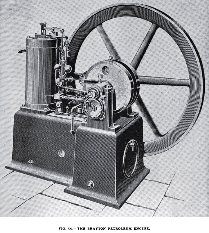
The Brayton petroleum engine, shown in Fig. 60, has already been illustrated and described in a separate
article in an earlier number of this magazine, but is here again incorporated for the sake of convenience and
completeness. The illustrations, while showing one of the older types of Brayton engines, used with very good results in the United States, perfectly represent the principles of operation.
The engine, as indicated by its name, belongs to the general class of petroleum engines, but in it no attempt is made to gasify or to vaporize, or even to heat the petroleum spray. The oil is finely divided—atomized in fact—in a large quantity of air, and is flashed into flame instantly. The combustion resembles that of ?our dust or coal dust, suspended in the air, and which is so rapid that it constitutes an explosion. The combustible material is divided into infinitely small particles, and each particle is surrounded with an ample supply of oxygen, to which it exposes a surface which is very great in relation to its bulk. Under these conditions combustion is exceedingly rapid, and spreads from particle to particle with amazing celerity. The oil is burned suspended in air; its combustion is complete, and is not impaired or delayed by metallic surfaces on which deposit can accumulate. The method of ignition is entirely novel. As the oil is not admitted till the moment of explosion, there is no question of “timing” valves, or of attaining a certain degree of compression before the charge can be fired. A brilliantly incandescent surface can be maintained in the cylinder all the time, ready to ignite the first drop of oil that comes in contact with it. To do this,
advantage is taken of the well-known phenomenon of flameless combustion, which is often shown on the lecture table, and but seldom found in practical work. A jet of air laden with hydrocarbon vapor is made to impinge continuously on a coil of platinum wire which has been previously heated, and as long as the jet is continued the platinum is maintained at a glowing temperature within the cylinder.
The engine works on a modification of the Otto cycle. Explosion, exhaust, suction, and compression follow each other in the usual order, but the suction is a suction of air only (not gas and air), and the compression, also a compression of air only. Further, the exhaust valve is held open during the early part of the compression stroke to "scavenge" the products of combustion out of the clearance space, and to replace them by air. As the oil is sprayed into the compressed air in the cylinder it requires a blast of high-pressure air to effect its entrance. This air is obtained from a pump, which also supplies air to the incandescent burner, a pressure of eighty pounds to the square inch being employed for this purpose.
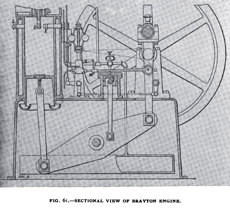
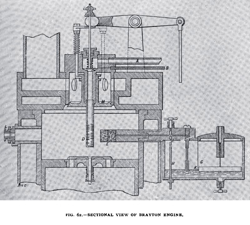
A sectional view of the engine is given in Fig. 61, while Fig. 62 shows some of the details. The general appearance of the engine is that of an inverted beam engine, the beam being enclosed within the bed, and having a connecting rod at each end of it. From an intermediate point in the beam is worked
the small pump which supplies the compressed air for spraying the charge and for maintaining the firing light. This pump is connected by a pipe to the cylinder head, shown on an enlarged scale in Fig. 62. The pipe A, together with the oil supply pipe B, discharges into a chamber, the bottom of which is closed by a valve C. When this valve is lifted, the oil is driven violently down the pipe, and through the circumferential cuts at its lower end, into the clearance space of the cylinder. The oil is finely divided by the action of the blast and is driven out at several different levels in minute particles.
The igniting device E is placed near to the sprayer D. The former consists of a tube in the end of which there are coils of platinum wire. These are separated from a packing of asbestos F by a perforated steel disc and a plate of wire gauze. A fine bore tube connects the firing device with the auxiliary oil reservoir G in which the oil is kept at a constant level by a float. Air from the pump is admitted to this reservoir by the pipe H ; part of it goes direct to the platinum burner through the adjustable cock J and part through the device K. This latter consists of a perforated vessel having an internal pipe, the lip of which is below the oil level, so that oil and air are driven upon it in spray to the asbestos pad F. The heat of the cylinder continually vaporizes the petroleum in the asbestos, and insures it being carried forward in gaseous form to
the platinum coils. In order to effect the preliminary heating of the platinum, there is provided opposite to it a door L with a glass-covered aperture in its centre. This door is opened, and a torch is inserted by which the platinum is raised to a red heat.
The oil pump M, Fig. 61, is operated by an eccentric driven by one to two gearing from the crankshaft. The exact length of stroke of this pump is determined by a wedge, which occupies a position in a slot between the ends of the eccentric-rod and of the pump plunger. When the engine is running above the normal speed, the wedge is raised by the governor; when it is running below the normal, the wedge is lowered and the stroke of the pump is nearly equal to that of the eccentric. A hand crank is provided, Fig. 60, by which the pump can be worked before the engine is started. On the same shaft with the eccentric is a cam for operating the oil inlet valve C, and the exhaust valve M. the former being opened when the left-hand end of the lever above it is raised, and the latter when it is depressed. The exhaust valve, as already stated, is opened at each revolution. It first evacuates the greater part of the products of combustion, and next it allows part of the air to blow through to scavenge the clearance space. This air is admitted by an automatic valve in the piston, Figs. 61 and 62, which opens as soon as a partial vacuum is formed in the cylinder. This position is chosen for the valve because the air can enter with little disturbance of the hot products of combustion, which congregate above, and can then sweep them completely out of the cylinder. To start the engine, the door L is opened and a torch of asbestos soaked in paraffin is introduced and placed beneath the burner E. When this is properly heated the torch is withdrawn and the door closed. A charge of oil is then injected by hand and the flywheel turned. On the compression stroke an explosion should occur, after which the engine runs without further attention. The cylinder is, of course, water-jacketed in the usual way. |
|
 1893 Brayton Petroleum Engine Co., Petroleum Engine
 1893 Brayton Petroleum Engine Co., Petroleum Engine (Sectional View)
 1893 Brayton Petroleum Engine Co., Petroleum Engine (Sectional View)
|
|