|
Title: |
1893 Article-Atlas Engine Works, Tandem Compound Steam Engine |
|
Source: |
Cassier's Magazine Sep 1893, pg. 336 |
|
Insert Date: |
11/28/2012 9:11:40 PM |
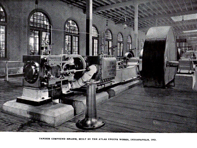
Two engines are exhibited by the Atlas Engine Works of Indianapolis, Ind., one of them representing a single and the other a double, tandem-com pound design. The cylinder dimensions are the same in each, 14x24 inches, with 30-inch strokes. Both engines are designed to run at 150 revolutions per minute, the single tandem-compound engine driving ten 50-light Thomson-Houston dynamos, while the double engine is connected to one of the large Westinghouse, 10,000-light incandescent dynamos, their rating being 500 and 1000 horse-power respectively. With the exception of the high-pressure cylinders, these engines are samples of the single valve automatic heavy-duty engine, which the makers have been building for several years. This engine has several notable features, among which are the massive bed-plate, the main bearing, with removable boxes, the peculiar form of cross-heads and the automatic dead wheel governor. This governor, like those of other builders, controls the engine by changing the throw and angular advance of the eccentric, but is so arranged that the action of the weights and springs is reinforced by the inertia of a heavy loose wheel, which gives it unusual power. The valve is a flat slide perforated by steam and exhaust ports, and relieved from pressure by a massive pressure plate. To meet the demand for engines of higher efficiency, the builders have compounded these engines, by adding high-pressure cylinders. These are of the four-valve type, there being separate steam and exhaust valves for each end. The cylinders are supported by feet on the foundations at the back of the single valve cylinders, which serve as the low-pressure cylinders. The high and low-pressure cylinders are connected by a distance piece so designed as to permit the removal of both cylinder heads and pistons without disturbing the connection.
The striking feature about the high-pressure cylinders is found in the valve gear, which is of a novel and unusual kind. The rather high speed at which the engines were designed to run, of course, precluded the use of the regular Corliss, or any form of releasing valve gear. The designer was, therefore, compelled to devise a positive motion which would accomplish the same results and be unaffected by the speed. This he has succeeded in doing in a very simple and effective manner. The valves are of a form for which the builders obtained a patent several years ago. They are like the Corliss, except that, like the seats, they are provided with a number of ports. This gives them the property of the well-known gridiron valve. The valve seats are sleeves or bushings forced into bored holes in the cylinder, and are removable when worn or injured. The ports are cut in the valves and seats by an index-milling machine, so that perfect correspondence is secured. At the same time, on the outer ends of the valve and seat, the ports are marked with the cutter, which affords a convenient and accurate means of ascertaining the set of the valves when the covering bonnet is removed. The valves have stems and supporting bonnets like in the Corliss arrangement, but instead of the usual catch blocks on the valve stem cranks, the crank pins carry steel cam rollers, about 2¼ inches in diameter by 1½-inch face, on anti-friction roller bearings. Instead of the Corliss wrist plate, there is a sliding piece supported by brackets on the cylinder between the valve bonnets. The stem of the low-pressure valve is prolonged through a stuffing box at the back of the steam chest and connects by means of a drop latch with a wrist on the sliding piece. This gives the sliding piece, when the engine is running, a reciprocating motion variable in extent with the throw of the eccentric of the shaft governor. On the sliding piece is mounted a set of cams which engage the rollers of the valve cranks and operate the valves. The cams are fastened to the sliding piece by bolts passing through slotted holes, which permit their adjustment. The steam valve cams are made in two parts so placed with reference to each other as to form a groove embracing the roller on the valve crank. This groove has two level portions joined by an incline.
Into the ends of the two parts of the cam are screwed studs connecting them by a yoke, the stem of which passes through a lug on the sliding piece. The nuts on the studs permit adjustment of the two parts of the cam to take up lost motion, and the nuts on the yoke stem provide for adjusting the whole cam when setting the valves. The motion of the cam slide is such that at the end of a stroke of the piston, the cam roller is just at the top of the incline of the cam groove. While the engine is passing the centre, the cam slide moves far enough to carry the roller down the incline and to open the valve. When cutting off at the shortest point, the cam slide moves only far enough to give the valve its full opening, and the eccentric, passing its centre, reverses the motion of the slide and immediately closes the valve. When the load requires a longer admission of steam, the governor increases the throw of the eccentric and the cam roll passes beyond the incline of the cam and runs upon the lower level, holding the valve wide open until, by the return motion of the slide, the incline is again reached, which shuts the valve and cuts off the steam. The roller then runs upon the upper level, holding the valve shut until the end of the return piston. The exhaust valve cranks are double-armed, one arm of each carrying a cam roller and the other two being connected by a parallel rod, which compels the pair of valves to move together. The opening of one valve shuts the other. The length of the parallel rod may be adjusted by means of right and left threads at the ends, so that the lap of each valve is greatest on the closing side. The effect of this is to close one valve just before the other opens, and the compression and release may by this means be made to occur at the desired points. The exhaust cams consist of a single piece each, acting on the upper side of the valve crank roller. Each cam opens the valve at its own end of the cylinder and closes the one at the other end. The effect of this arrangement is that while the point of closure of the steam valves varies as determined by the governor, the exhaust valves, though operated by the same eccentric, have a uniform motion, opening and closing at the end of each piston stroke. Indicator cards taken from one of these engines show the distribution of steam to be nearly perfect. By means of the drop-latch the cam slide may be disconnected from the eccentric, and a starting bar is provided by means of which the valves may be worked by hand to back the engine off the centre in starting. The whole arrangement is neat in appearance and noiseless in action. |
|
 1893 Atlas Engine Works, Tandem Compound Steam Engine
|
|