|
Title: |
1893 Article-New York Safety Steam Power Co., High-Speed Automatic Steam Engine |
|
Source: |
Cassier's Magazine Jul 1893, pg. 223 |
|
Insert Date: |
11/22/2012 8:39:34 PM |
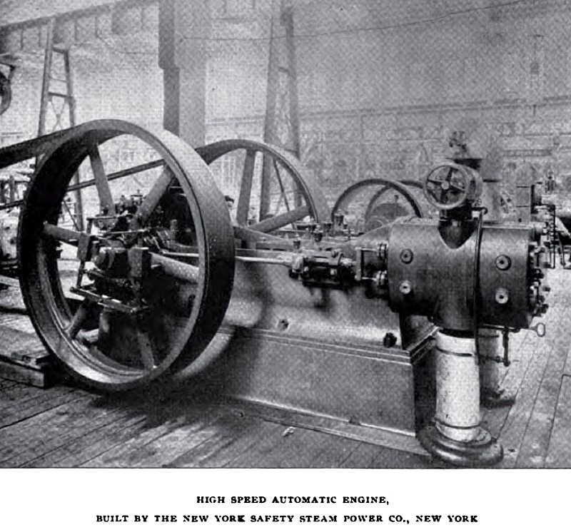
A further contribution to the high-speed, automatic engine exhibit is made by the New York Safety Steam Power Company, of New York, one of whose centre-crank engines, slightly different in point of valve detail from the company's standard type, is shown driving some electrical machinery. In this engine, as in the one just described, a relatively small degree of clearance is secured by having the steam ports close to the ends of the cylinder. Unlike the standard type engine, which has only one main valve, the engine on exhibition has two main valves, or, perhaps more correctly speaking, the main valve is made up of two parts, the detail view shown being a longitudinal section through one of them. Each of the parts has its separate valve stem, and the two stems, in turn, are connected and driven by one eccentric rod as shown in the general view.
The valves are of the balanced piston type and are controlled with corresponding ease by the governor. The paths of the live and exhaust steam in getting to and from the cylinder need no special explanation; the sectional view tells its own story.
The main valve stem which works the two valves through the intervention of the two subsidiary stems connected, as already stated, by a crosspiece, passes through an accurately squared cross-head, which slides in a long squared guide, f1rmly f1xed to the engine frame. This cross-head has a steel pin projecting from one side, which takes the eccentric rod; thus but one pin-journal is employed between the valve stem and the eccentric.
In the governor two eccentrics are used. The main eccentric has a slotted arm, which projects radially and is hung upon a pin, or shaft, having a bearing in the governor frame, as shown above. The secondary eccentric shaft, located below, carries two arms, which are connected by links to the levers supporting the governor weights; the other end of the shaft is a small eccentric, which fits into a block which has vertical play between guides affixed to the arm of the main eccentric.
The action of the governor is as follows: When the engine is at rest, or is moving at a speed so slow that the tension of the spring overcomes the centrifugal force of the weights, the centre of the main eccentric is at its extreme point distant from the centre of the shaft, and the valve has its greatest travel, the steam being allowed to follow the piston to nearly seven-eighths of the stroke. As the engine increases in speed, and the centrifugal force of the weights overcomes the tension of the spring, the cam is slightly turned to its block, and throws the centre of the main eccentric nearer and nearer to the centre line of the crank, until the desired speed is attained. When the limit of its throw is reached, the travel of the valve is only equal to the lap and lead of the valve. The leverage being great, and the eccentricity of the cam being very slight, but little force is necessary to partly rotate the cam and move the main eccentric.
On the other hand, the resistance of the cam to any opposite force is so great that, when connected, the main eccentric cannot be shifted, except by reason of the movement of the weights and lever connections of the cam shaft. The swinging of the eccentric causes the lead to increase as the travel of the valve shortens. The speed of the engine may be varied either by change in the tension of the one spring employed, or by change in the position of the weights, or both. The direction in which an engine shall run is also within the control of the engineer, and the changes necessary to reverse can be quickly made. The governing mechanism is an independent part of the governor wheel, complete in itself, and can be applied without much trouble to any other wheel, should it become necessary or desirable to make a change in size.
The engine frame is cast in one piece, embracing all the bearings of the engine, and a drip pan extends around the bottom edge to collect oil and water drippings and carry them to a common point of discharge. The engine shown at the Fair has a 15½ x 16-inch cylinder, runs at a speed of 250 revolutions per minute, and is rated at 150 horsepower. |
|
 1893 New York Safety Steam Power Co., High-Speed Automatic Steam Engine
|
|