|
Title: |
1893 Article-Ball & Wood Co., Tandem-Compound Steam Engine |
|
Source: |
Cassier's Magazine Jul 1893, pg. 221 |
|
Insert Date: |
11/22/2012 8:36:19 PM |
A feature of these engines which at once attracts attention is the arrangement of the low-pressure valves. It will be observed that the valve chest on the low-pressure cylinder is cylindrical in shape, and is placed transversely to the axis of the cylinder, and directly underneath it. In the sectional view, small arrows in the passages indicate the direction of the flow of the steam, and larger arrows in the moving parts show the direction of their motion. The valve chest is made very large in diameter, so that the steam ports are short and direct. Two double-ported valves, with arc-shaped faces fitting the bore of the valve chest, are placed opposite each other and are mounted loosely on a central valve stem which drives them both and allows both to be held in contact with their faces by steam pressure. Steam is admitted from the valve chest over the edge on the end of the valve, and also through the port in the valve, thus giving a very rapid and wide opening. At the same time the exhaust from the other end of cylinder, has a very direct passage to the condenser. The valve stem carries on its outer end a rock arm which receives motion from a simple crank pin on the outside of the balance wheel, thus dispensing with an eccentric and having all the parts easily accessible. The whole valve mechanism is made very simple by this arrangement, the number of parts is small, and the valves, as already intimated, give a wide and quick opening and follow up their wear with steam pressure. The clearance also is small owing to the short and direct ports, which, moreover, are so located, as will be understood from the illustration, that they readily drain away water accumulations from the cylinder and reduce the chances of accident from such accumulations.
The valve on the high-pressure cylinder is substantially the same as that used in the Ball engine, described in the preceding paper. An additional view of it is given here, together with a view of the inside of the high-pressure valve chest. It may not be amiss to repeat that the valve is made in two parts, with telescopic sleeves connecting them and allowing the valve faces, which are opposite each other, to be held against their respective seats by steam pressure. The steam, it must be remembered, is admitted to the lights used in the Exposition grounds. General and detail views of the cross-compound and of one of the tandem-compound engines are given in this number. A feature of these engines which at once attracts attention is the arrangement of the low-pressure valves. It will be observed that the valve chest on the low-pressure cylinder is cylindrical in shape, and is placed transversely to the axis of the cylinder, and directly underneath it. In the sectional view, small arrows in the passages indicate the direction of the flow of the steam, and larger arrows in the moving parts show the direction of their motion. The valve chest is made very large in diameter, so that the steam ports are short and direct. Two double-ported valves, with arc-shaped faces fitting the bore of the valve chest, are placed opposite each other and are mounted loosely on a central valve stem which drives them both and allows both to be held in contact with their faces by steam pressure. Steam is admitted from the valve chest over the edge on the end of the valve, and also through the port in the valve, thus giving a very rapid and wide opening. At the same time the exhaust from the other end of cylinder, has a very direct passage to the condenser. The valve stem carries on its outer end a rock arm, which receives motion from a simple crank pin on the outside of the balance wheel, thus dispensing with an eccentric and having all the parts easily accessible. The whole valve mechanism is made very simple by this arrangement, the number of parts is small, and the valves, as already intimated, give a wide and quick opening and follow up their wear with steam pressure. The clearance also is small owing to the short and direct ports, which, moreover, are so located, as will be understood from the illustration, that they readily drain away water accumulations from the cylinder and reduce the chances of accident from such accumulations.
The valve on the high-pressure cylinder is substantially the same as that used in the Ball engine, described in the preceding paper. An additional view of it is given here, together with a view of the inside of the high-pressure valve chest. It may not be amiss to repeat that the valve is made in two parts, with telescopic sleeves connecting them and allowing the valve faces, which are opposite each other, to be held against their respective seats by steam pressure. The steam, it must be remembered, is admitted to the interior of sleeves and thence through the ports into the cylinder, from which it is exhausted past the ends of the valve into the steam chest and out through the exhaust pipe at the bottom. The diameter of the sleeves, of course, determines the amount of pressure with which part of the valve is held to its seat. A judicious choice insures just enough pressure for good contact and not enough to cause undue friction and wear. The main features of the governor of the engine are well shown in the annexed engravings. The hub of the governor wheel is shown with the eccentric A bolted to its outer end, and forming practically part of it. The eccentric strap B is made in halves, and is held in place on the eccentric by a flange on one side and a plate, C', on the other. The governor weights are connected by links, D, to studs in the sides of the eccentric strap, so that the strap and the plate Care turned slightly around the eccentric by the radial movement of the weights. Motion for the valve is taken from the crank pin, E. Since the radial movements of the weights turn the plate C around its centre, which is eccentric to the shaft, the pin E naturally is moved through the arc of a circle whose centre is the centre of the plate. The curved path of the crank pin E is made to give almost a constant lead to the valve until a very early cut-off is reached, when the lead rapidly disappears. It will be seen that only two moving surfaces are interposed between the shaft and the road, which actuates the valve. Of these the crank pin if is practically the only wearing surface, as it is the only one constantly in motion relatively to the surfaces with which it is in contact. The other, the eccentric strap, moves on the eccentric only when the weights change their position. |
|
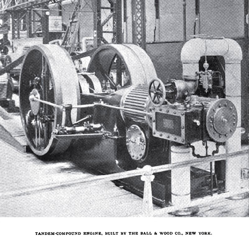 1893 Ball & Wood Co., Tandem-Compound Steam Engine
|
|