|
Title: |
1893 Article-McIntosh, Seymour & Co., Double Tandem-Compound Steam Engine |
|
Source: |
Cassier's Magazine Jul 1893, pgs. 216-218 |
|
Insert Date: |
11/20/2012 9:50:46 PM |
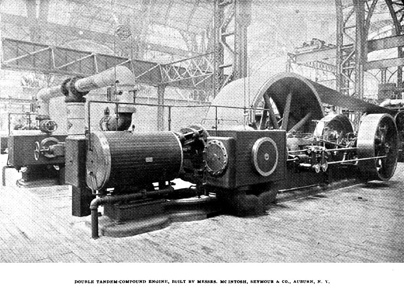
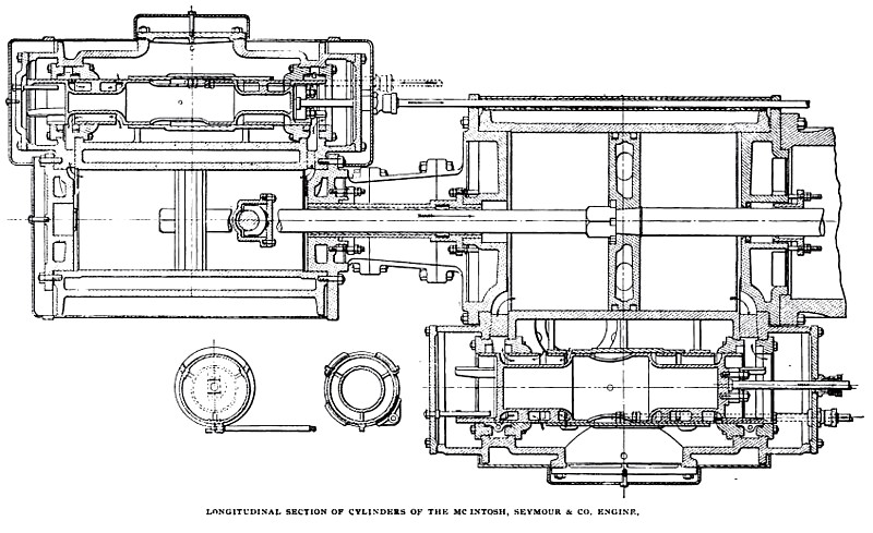
Prominent among the special designs of which several illustrations have already been given in the preceding papers, is a 1200 horse-power, double tandem compound engine, built by Messrs. McIntosh, Seymour & Co., of Auburn, N. Y. The high pressure cylinders of this engine measure eighteen, and the low pressure cylinders, thirty-two inches in diameter, while the stroke amounts to three feet. A speed of 112 revolutions per minute is maintained. The sectional view, which is given of one of the pairs of cylinders, will help to give a better idea of some of the principal details of the design.
Between the high and low pressure cylinders there is what the builders call their split connecting head and metallic packing sleeve. This sleeve is lined with compressed Babbitt metal, and is bored out to exactly fit the piston rod, which runs in it. The self-adjusting block, as is shown in the section through the tube, takes up wear, should any occur, from the weight of the rod and pistons. The bearing surface of the piston rod on the packing sleeve is nearly as great as that of the cross-head, and forms a good method of guiding the pistons and supporting their weight, allowing them to be suspended exactly central in the cylinders. The piston rod being steered at two points, that is, the pack1ng tube and the cross-head, at some distance from each other, makes the running of the engine very smooth. The packing sleeve also does away with all stuffing boxes between the two cylinders, and is arranged so that it can be pushed into the high-pressure cylinder by loosening up the packing gland. By removing the distance pieces in the split connecting heads, the low-pressure cylinder heads can thus be slid away from the low-pressure cylinders, and the latter are made easily accessible without disturbing the high-pressure cylinders in any way. All the cylinders are provided with relief valves of special design, which can be set to open automatically at any desired pressure, and at the same time can be opened by hand, serving as cylinder cocks.
The main valves of the engine are of the piston type, with the two ends extended to meet in the centre, so that when one of them is opened on the steam end, the port connects, not with the steam chest, but with the central space in the valve, ports being cut through from this space to the exterior to connect with the steam chest proper. On the outside of the valves in the steam chests ride simple sleeves which serve as auxiliary cut-off valves, and arc directly under the control of the governor, being, thus, automatic in their action. The main valve on each cylinder is driven by a fixed eccentric. The main valve seat consists of a ring, or rather two rings, made in one piece and connected by several bridges across the port-opening which the space between them forms. The seat is crescent shaped, split and adjustable to fit the valve, by the stem which extends to the upper side of the steam chest, where it can be turned by a box wrench. The adjustment can be easily and quickly made.
The governor is very similar to the governor used on the single cylinder engines built by the same firm, except that the eccentric, instead of being moved across the shaft, is simply rotated about it by the action of the governor weights, correspondingly changing the point of cut-off. A plate spring is used in the governor. Both sides of the engine are operated from the same governor through the intervention of a rock-shaft, which extends across and drives the cut-off valves on the further side.
An especially noteworthy feature of these engines is found in the fact that auxiliary shafts are used to carry the governor and eccentrics, and also the transmission gear wheel driving the condenser. These auxiliary shafts are driven by means of drag links which, in turn, receive their motion from extensions of the main crank pins, the object of the whole arrangement having been to reduce the sizes of the different parts of the valve gear and to correspondingly decrease their friction. The governor, in virtue of this feature of the design, also is brought down to a smaller size than usual, and is more sensitive and will act more quickly than 1f it were mounted on the main shaft. The cut-off valves are, to a certain extent, cylindrical grid-iron valves, as will be understood from the sectional view. The high pressure cylinders are provided with steam jackets, and the receivers between the cylinders are filled with copper heating coils, presenting a large amount of heating surface, and tending to give perfectly dry steam at the entrance to the low pressure cylinders. The builders argue that the cause of inefficiency of steam jackets on high pressure cylinders, as ordinarily made, is lack of proper circulation through the jackets, and that a very rapid circulation is necessary to render them operative. By the present arrangement the temperature of the steam in the receiver being much lower than that in the coil, a very considerable amount of condensation takes place in the receiver coil, and as this is fed from the high pressure cylinder jacket only, a brisk circulation is insured in the latter. The pipes from the high-pressure cylinders to the receivers are also fitted with steam separators to catch any water, which may be carried along by the passing steam.
The main shaft of the engine is made of hammered wrought iron, measures fourteen inches in diameter in the main bearings, sixteen inches in diameter between them, and weighs about 33,000 pounds. The main bearings, which are twenty-four inches long, are provided with water jacket shells lined with Babbit metal. The lower one in each case is machined on the outside to the shape of a true sphere, and the bed frames are recessed to correspond. In this way a ball and socket bearing is formed for each journal, insuring uniform distribution of pressure over its surface.
Through bolts, tightened up after the bearings have been allowed to align themselves properly, fasten the latter securely to the frame. The shells are provided with cheek pieces for taking up wear horizontally, and can be slid around and taken out in a few minutes by jacking up the shaft enough to take the weight off the bearings. The lower cross-head guides also are water-jacketed, being cored out for this purpose. They are separate from the frame. Underneath the bearings, and cast in the frame, is a large oil-settling chamber. Bronze rings are placed on the shaft at the end of the journals, which throw all oil fed to the bearings into channels and lead it into this settling chamber, which is provided with a gauge glass showing the amount of oil in it. A small eccentric on the drag link shaft above mentioned drives an oil pump, the suction pipe of which is connected with the oil-settling chamber, while the delivery pipe feeds the oil to the upper sides of the journals. This oiling device appears to be eminently satisfactory in its operation. The oiling, it will be understood, is continuous and automatic, and the bearings are kept practically flooded. The engine frames extend out under and support the high-pressure cylinders, and the latter are bolted to them, but still are free to move longitudinally to compensate for expansion and contraction of the cylinders with varying temperatures. The fly-wheel is not the least interesting part of the engine, being cast in four pieces, with two sets of arms; in fact, it is practically made up of two wheels, placed side by side upon the shaft and bolted together. Each of these four pieces is cast separately, planed up, and bolted together by reamed bolts, the splits in the rim of each half being placed opposite each other. The wheel is prevented from bursting by twenty-four three-inch bolts at the rim, and sixteen two and five-eighth inch bolts at the hub. This, of course, does not include bolts holding the hub and rim together laterally. The rims are provided with broad internal flanges in the centre and at the edge for stiffening the wheel and preventing oil from getting on the belts. The wheel is sixteen feet in diameter, and seventy-eight inches broad, and weighs 62,000 pounds. The total weight 0f the engine is 250,000 pounds. |
|
 1893 McIntosh, Seymour & Co., Double Tandem-Compound Steam Engine
 1893 McIntosh, Seymour & Co., Double Tandem-Compound Steam Engine (Longitudinal Sectionof Cylinders)
|
|