|
Title: |
1868 Article-Gould Machine Co., Meinard's Combined Planer & Slotting Machine |
|
Source: |
Scientific American, V 18 #6, 08 Feb 1868, pg. 81 |
|
Insert Date: |
11/3/2012 8:01:42 PM |
Improvement on Iron Planers.
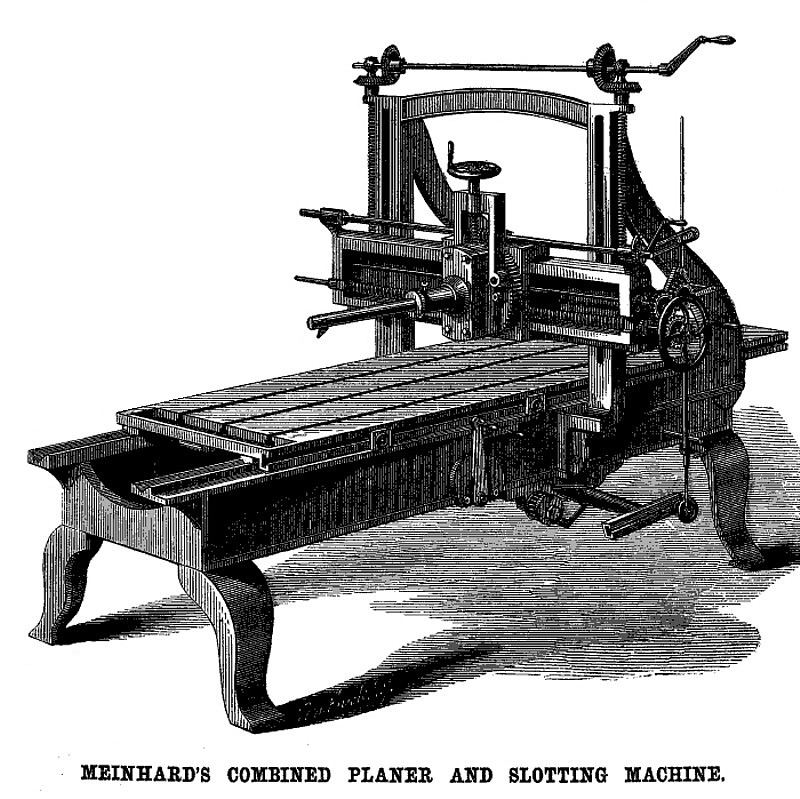
The hand planer and shaping machine are often used instead of the power planer, because the latter could not be easily adapted to the style of work desired when the surface to be planed was angular, slashed, or of a partially circular form. The attempt of the inventor of the improvement intended to be represented in the accompanying engravings, is to adapt the ordinary planer to a class of work now generally done on the hand planer, slotter, and shaping machine. It is of such a character as to be readily attached to any planer, and in no wise impairs its normal efficiency. It is the invention of Charles A. Meinhard, of Fort Wayne, Ind., and was patented through the Scientific American Patent Agency, Nov. 26, 1867.
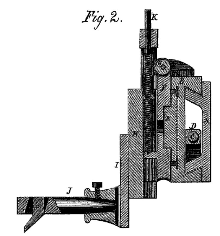
In addition to the work usually performed by the ordinary planer, this appurtenance will enable the operator to work on angular and curved surfaces, or to cut the slots and key-ways in taps, reamers, shafts, or pulleys, and other useful adaptations will suggest them- selves to the practical mechanic. Fig. 1 is a perspective view of the planer having this attachment; Fig. 2 being a section of the head and its appurtenances. The letters refer to the latter alone, as their connection with the main figure can easily be traced. A is a frame on which slides the head, B, having dovetailed lips fitting corresponding surfaces on the frame, A. This head, with its connections, is moved transversely across the bed of the planer on the frame, by the screw, C, which works in a nut, D, formed on the inner side of the head, B, so that by turning the screw, C, the head, B, can be worked transversely across the planer as with the ordinary head. On the outer side of the head or plate, B., is formed a circular T-shaped groove, and concentric with it is a circular projection, E. F is a solid worm wheel, having a recess on its inner face, fitting the projection, E, and held by bolts with T-shaped heads fitting the circular groove in B. The shaft, G, which passes, like the screw, C, across the frame, is slotted or grooved from end to end, and carries a worm engaging with the worm wheel, F, and turning with the shaft, G, by means of a feather, key, or pin. It is kept in contact with the teeth of the worm wheel by projecting ears on B. On the face of the worm wheel is a dovetail tenon upon which a correspondingly grooved plate, H, slides. To this plate is bolted the tool holder, I, and a serew, K, serves to elevate or depress the planing or slotting tool by means of the plate, H. The cylindrical tool holder, J, holds the cutter, which is pivoted in a slot and is held in position by a light spring which allows it on the return stroke, to ride over obstacles, but returns it to place on the forward movement.
It is evident to the practical mechanic that not only the transverse movement of the cutter head can be controlled by an automatic feed, but that the position of the tool to necessary angles or curvatures can be similarly controlled; so that a planer, with this device attached, may by used to plane around surfaces which present a form varying from the level. The tool-holding plate, I, may be at any, time removed and another substituted to suit any style of work. As every practical machinist will readily understand the object and construction of this planer, from the engravings, it will not be necessary to give a more detailed description.
Further information, however, in regard, to rights may be obtained of the patentee, Charles A. Meinhard, Fort Wayne,
Patent #71,401 |
|
 1868 Gould Machine Co., Meinard's Combined Planer & Slotting Machine
 1868 Gould Machine Co., Meinard's Combined Planer & Slotting Machine (Tool Holder)
|
|