|
Title: |
1898 Article-Mietz & Weiss, Gas & Oil Engines |
|
Source: |
Gas, Gasoline and Oil Vapor Engines, 1898 pgs 320-321 |
|
Insert Date: |
10/27/2012 12:46:26 PM |
The Mietz & Weiss Gas and Oil Engines
The gas engine of the Weiss patents is built by August Mietz, No. 87 Elizabeth Street, New York City. It is of the two-cycle type, taking an impulse at every revolution. It has an enclosed crank chamber with a supplementary small cylinder containing a free moving piston counterbalanced by a spring. An opening into the crank chamber under the piston produces compression of the gas in the upper part of the small cylinder by the air pressure in the crank chamber during the impulse stroke and so feeds the gas charge with equal pressure with the air charge made by the outward stroke of the piston. The air charge enters through a port in the cylinder opened at the inward stroke of the piston, which produces a slight vacuum in the crank chamber and thereby causes the air to rush in while the port is open. The return or impulse stroke compresses the air in the crank chamber, which in turn compresses the gas by the movement of the small free piston.
By the opening of a charging port in the cylinder by the piston at the end of its impulse stroke the compressed charge of air and gas enters the cylinder. A larger cylinder-port opening just before the end of the stroke exhausts the cylinder of the products of the burned gases. A projection or deflector on the piston directs the incoming charge towards the head of the cylinder. The charge of gas is made through a small poppet-valve operated by a push-blade, rock-shaft lever, and an eccentric on the main shaft.
The governing is by the inertia of a weight adjustable as to its position on the push-blade arm by a screw thread, and by the motion of the arm the weight rides up an incline and is released at the top of the incline to fall by gravity and catch the blade of the gas-valve.
An excess in speed sends the weight too high to catch the valve stem and a mischarge is made. The hot-tube igniter is a novelty in its line. The tube is made of lava 4 inches in length and perforated with a central hole from end to end. It is held in sockets with asbestos washers and a screw clamp; the chimney being held by a lug with a clear opening at the bottom for the in-draft of air, at which point the gas jet is located, as shown in Fig. 244.
The kerosene oil engines are built on the same general plan of the gas engine, only displacing the ignition device in the cylinder for a conical internally flanged vaporizer and igniter, upon the flanges of which the oil is projected in small and definite quantities by the action of a small plunger held back by a spring and pushed forward by the governed push-blade, as in the gas engine. A small valve at the pump cylinder terminus, held back by a spring, limits the amount of oil injected to the exact volume of the plunger stroke. The air charge is exactly the same as described for the gas engine.
To start the oil engine the conical vaporizer is heated by a lamp to the proper temperature to induce ignition of the internal mixed vapor and air by the increased heat of compression, when the engine becomes self-acting by a turn of the fly-wheels.
In the experimental work of Mr. C. W. Weiss, he has carried the compression in the kerosene engine up to 400 lbs. per square inch, at which pressure a very strong engine must be used; but with runs at 100 and up to 250 lbs. compression pressure, a remarkable economy in fuel has been obtained; the combustion being so perfect that no residues are found in the combustion chamber, cylinder, and exhaust. |
|
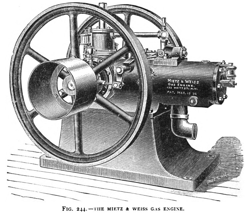 1898 Mietz & Weiss, Gas Engine
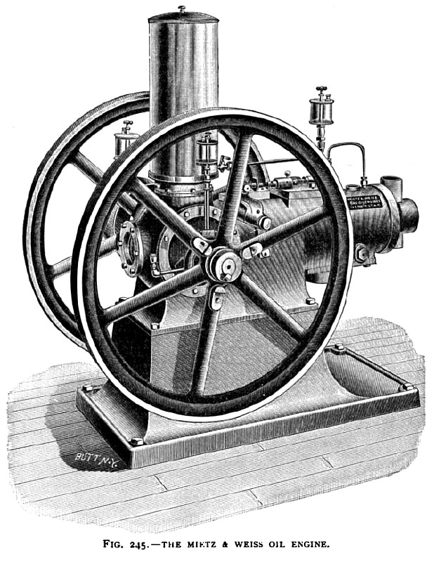 1898 Mietz & Weiss, Oil Engine
|
|