|
Title: |
1898 Article-Priestman & Co., Oil Engine |
|
Source: |
Gas, Gasoline and Oil Vapor Engines, 1898 pg s247-248 |
|
Insert Date: |
10/23/2012 8:26:17 PM |
The Priestman Oil Engine
This has been long in use in Europe, and for several years past has been largely improved by the American builders, Priestman & Co., who have introduced a new system for perfecting the atomization of crude and kerosene oils, or any of the cheap distillates of petroleum. By the system adopted in this engine, perfect combustion is produced; ignition is made positive, and the fouling of the cylinder and valves is obviated to such extent as to require cleaning only at periods of several months. The low cost of the heavier petroleum distillates used makes the cost of power the lowest that can be obtained in an explosive motor.
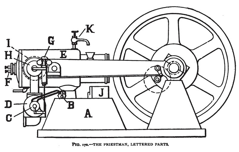
In the cut, Fig. 172, A is the oil tank filled with any ordinary high test (usually 1500 test) oil, from which oil under air pressure is forced through a pipe to the B three-way cock, and thence conveyed to the C atomizer, where the oil is met by a current of air and broken up into atoms and sprayed into the D mixer, where it is mixed with the proper proportion of supplementary air and sufficiently heated by the exhaust from the cylinder passing around this chamber. The mixture is then drawn by suction through the I inlet valve into the E cylinder, where it is compressed by the piston and ignited by an electric spark passing between the points of the F ignition plug, the current for the spark being supplied from an ordinary battery furnished with the engine, the G governor controlling the supply of oil and air proportionately to the work performed. The burnt products are then discharged through the H exhaust valve, which is actuated by a cam. The I inlet valve is directly opposite the exhaust valve. The J air pump is used to maintain a small pressure in the oil tank to form the spray. K is the water-jacket outlet.
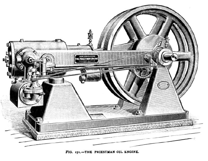
Fig. 171 illustrates the general features of this engine. It is built on the straight-line principle, by which the moment of greatest strain from the power impulse is met by the frame in direct lines between the points of pressure.
The design is of the four-cycle compression type, with poppet valves, and its regulation is by varying or cutting off the supply of atomized oil. The oil fuel is placed in the base of the engine in an air-tight chamber, A in Fig. 172. A small air-pump, J, operated from the reducing-gear shaft forces air into the oil chamber with a pressure sufficient to cause the oil to be lifted to the three-way adjusting cock B, which also admits air from the compressed air in the oil tank; and oil and air pass to the atomizer through two small pipes, where their proportion and quantity are regulated by the governor. |
|
 1898 Priestman & Co., Oil Engine
 1898 Priestman & Co., Oil Engine (Lettered Parts)
|
|