|
Title: |
1898 Article-P. F. Olds & Son, Gas Engine |
|
Source: |
Gas, Gasoline and Oil Vapor Engines, 1898 pgs 238-239 |
|
Insert Date: |
10/23/2012 5:17:36 PM |
The Olds Gas and Gasoline Engine
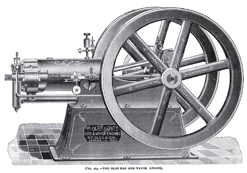
We illustrate in Fig. 164 the latest design of gas and gasoline engines built by P. F. Olds & Son. These engines are of the four-cycle compression type, with poppet valves larger than the usual size to facilitate the exhaust and charge, and to avoid the counter-pressures usual with small-sized valves.
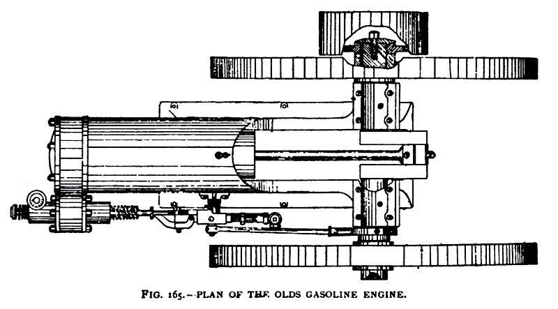
The valve gear is a simple eccentric on the main shaft connected by a rod to a slide bar, moving in a bracketed box at the side of the cylinder. The slide bar carries a revolving alternating or toothed wheel, the alternating motion of which is governed by a pendulum swinging upon a concentric pivot.
The ratchet and toothed wheel are pivoted to the slide, and the teeth become push-pins to the spindle of the exhaust valve, and are made to open the exhaust regularly at normal speed and make a miss by throwing the notch in the wheel opposite the spindle when the speed is above the normal. By throwing out the pawl, which operates the alternating wheel, compression will be omitted by the open exhaust, and the engine can be easily turned to any point for starting without the resistance of compression.
The inlet valve is opposite and in line with the exhaust valve, and is opened by the suction of the piston. The vaporizing chamber for gasoline is in front of the cylinder head, and receives near its bottom the air pipe from the engine-bed frame.
When running with gasoline, a small pump is operated by the eccentric rod, which supplies a small reservoir over the inlet valve, arranged so that the surplus runs back to the reservoir below the level of the pump, thus avoiding the possibility of accidental overflow of gasoline. On the top of the reservoir is a sight glass that shows the flow of the gasoline, with a set valve to regulate the feed to the mixing-chamber, where it is atomized by the inrush of air to the cylinder during the charging stroke.
The igniter is by hot tube or electric, preferably a hot tube, with some special improvements that make this style of ignition very desirable. The igniters are not shown in the cut, but occupy the place of a plug seen on top of the valve chamber.
This company also makes a vertical engine on the same principles as the horizontal one, in sizes of from 1 to 5 H. P. Their horizontal engines are made in five sizes, from 7 to 50 B. H. P. Also double-cylinder launch engines and launches—2 H. P. for 18- and 20-foot launches, 4 H. P. for 25-foot, and 8 H. P. for 35-foot launches. In these launch motors the gasoline for a day's run is stored in an iron receptacle at the motor, thus avoiding all danger from pipes and separate tank leakage.
In these boats the engine is not required to be set exactly in line with the propeller shaft. A reversing friction-clutch is used with a flexible shaft connection, so that the setting of the engine and shaft in any boat is an easy matter. The cooling water from the cylinders is discharged through the exhaust pipe, which is a rubber hose passing out at the stern. By this arrangement the rubber exhaust pipe is kept cool, and its flexibility makes a silent exhaust. |
|
 1898 P. F. Olds & Son, Gas Engine
 1898 P. F. Olds & Son, Gas Engine (Plan View)
|
|