|
Title: |
1898 Article-Fairbanks Morse & Co., Large Gasoline Engine |
|
Source: |
Gas, Gasoline and Oil Vapor Engines, 1898 pgs 181 & 182 |
|
Insert Date: |
10/22/2012 8:18:51 PM |
The Fairbanks-Morse Gas Engine
The engines of Fairbanks, Morse & Co. are all of the four-cycle compression type. The horizontal style is built in eleven sizes, from 3 to 70 n. H. P., and the vertical style of 2 B. H. P. The design of these engines, which is mostly based on the Caldwell-Charter patents, has a simplicity of construction in which the least number of moving parts has been a leading feature.
The valves are of the poppet type, the exhaust valve being operated by a direct line push-rod with a roller contact with the cam on the secondary gear; the roller being thrown on or off the cam by a bell-crank arm moved by the governor.
The governor is of the centrifugal type attached to the flywheel, counterbalanced by spiral springs and made adjustable by set nuts.
To the exhaust valve push-rod is attached an arm that operates the gas inlet-valve in connection with the air pipe extending from the base of the engine. The gas valve has an index valve to regulate the flow of gas.
A mixing-chamber in the head of the cylinder is insulated from the combustion chamber by an inlet-check valve, self-operating, held to its seat by a spring, and entirely enclosed within the mixing-chamber by the flanged projection from the cylinder head. This arrangement makes this a free-working valve and avoids leakage or undue friction.
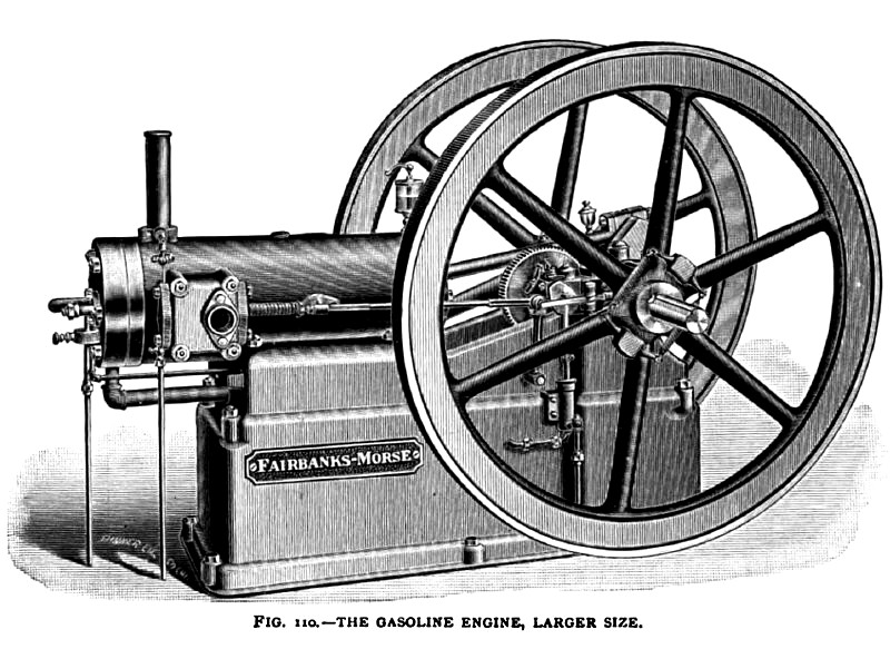
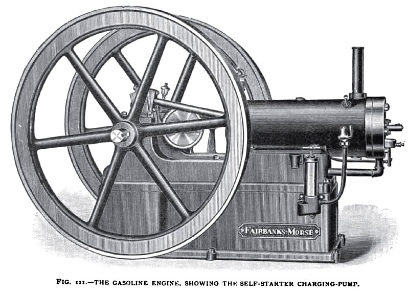
Hot tube and electric ignition are used as preferred. The electrodes are located in the head of the cylinder, with its sparking-device operated by the exhaust-valve push-rod through a second push-rod and arms. The engine as arranged for gas is shown in Fig. 107. The gasoline engines (Figs. 108, 109, 110, and 1n) of various sizes represent the arrangement for gasoline. They have a gasoline pump attached to the base of the engine directly under, and driven by a crank pin on the face of the exhaust eccentric. The pump drawing a supply from a tank placed in a safe place below the level of the pump, discharges into a small reservoir (P in Fig. 109, and also shown in the cylinder heads of Figs. 108 and no), and overflows the surplus back to the tank. A small valve K in the reservoir P regulates the flow of gasoline to the mixing-chamber. In the air pipe is a nozzle leading to the reservoir P, and the in-going air draws from the nozzle the proper amount of gasoline to form a perfectly combustible mixture of gasoline and air.
Each suction of the engine draws up fresh gasoline from the reservoir P, and always the same quantity, as controlled by the supply or throttle valve K.
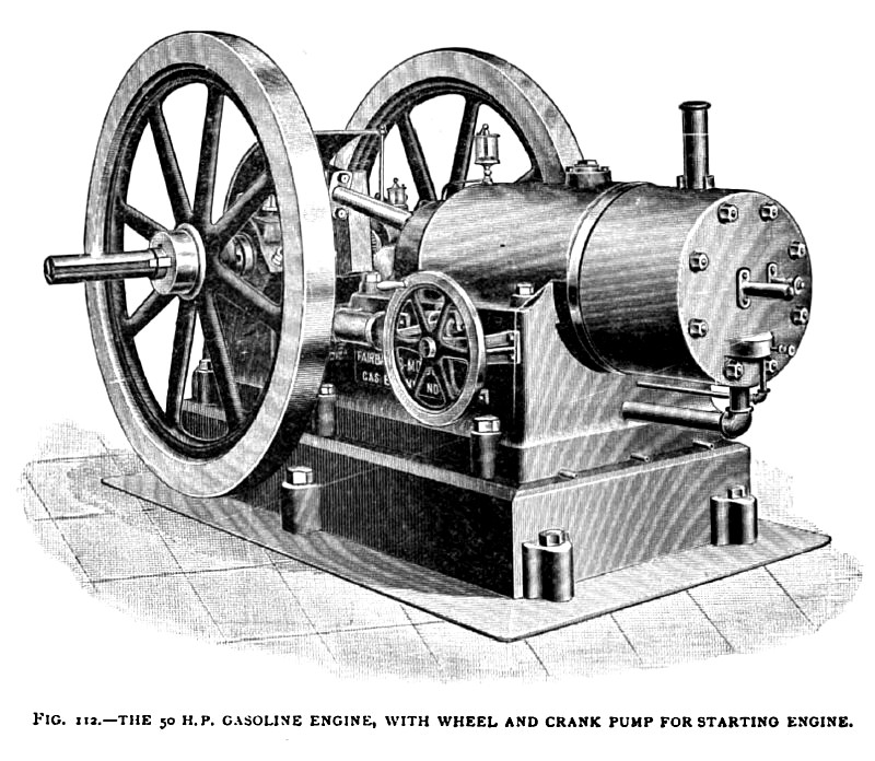
The self-starting devices are shown in Figs, 111 and 112, and consist of a small hand air-pump for medium-sized engines, and a hand crank pump on the larger size attached to the base of the eng1ne. A small receptacle in the base of the pump is charged with gasoline of sufficient quantity for a single engine charge. The operation of the pump then charges the cylinder, and a match exploder fires the charge. |
|
 1898 Fairbanks Morse & Co., Large Gasoline Engine
 1898 Fairbanks Morse & Co., Large Gasoline Engine (Rear)
 1898 Image-Fairbanks Morse & Co., 50 H. P. Gasoline Engine
|
|