|
Title: |
1906 Article-Cincinnati Milling Machine Co., #5 Plain Horizontal Milling Machine |
|
Source: |
Page's Engineering Weekly, 12 Jan 1906, pgs 80-81 |
|
Insert Date: |
6/6/2012 8:35:10 AM |
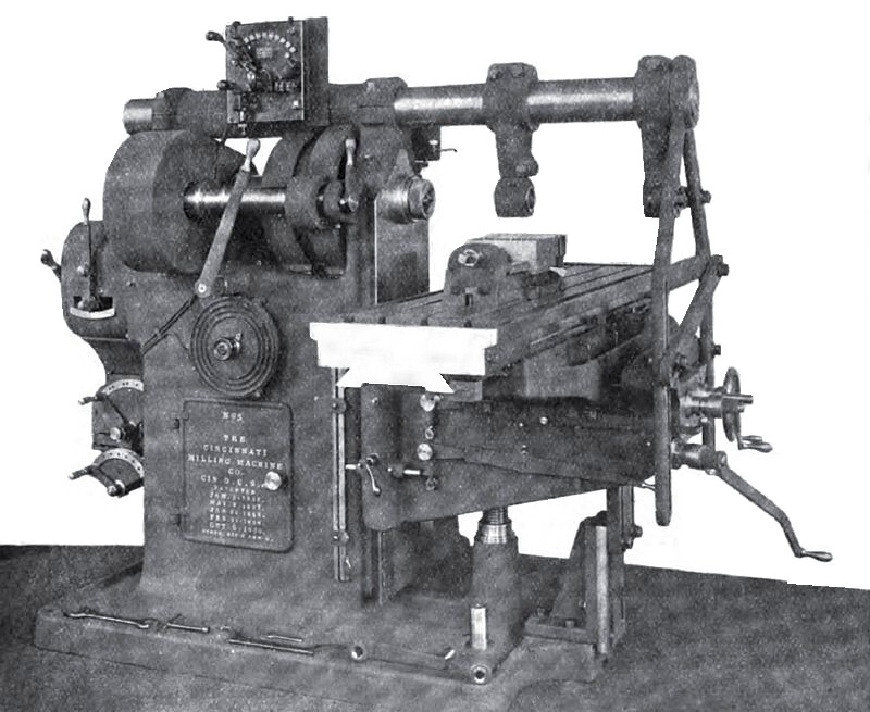
No. 5 PLAIN MILLING MACHINE BY THE CINCINNATI MILLING MACHINE COMPANY
The above company has recently added several new sizes to their series of plain millers bringing the number up to nine. Among recent improvements are a new back-gearing arrangement and a new knee. The No. 5 machine illustrated herewith (fig. 1) is the largest size of plain machine designed by them for a general line of heavy milling. Among the features common to these machines attention may be called to the following points :—
Any adjustment of the operating levers and handles can be made or any of the feeds can be reversed without the necessity of the operator changing his position. Two adjustments may be made simultaneously. The advantages of such an arrangement are obvious in any class of milling, but are especially marked in jig milling where the feeds are short and fast, when the time consumed in making adjustments and reversing feed is reduced to a minimum.
The spindle is made of crucible steel and has a hole through its entire length. The front end of spindle is threaded to receive a chuck or large cutter. A cover is provided for protecting the thread.
The machines are provided with ample spindle power and thoroughly adapted for the use of high-speed steels. We are informed that the positive feed mechanism with which the Cincinnati Company replaced feed belts five years ago on all back-geared machines, has proved entirely satisfactory in every particular, the rate of feed being changeable in an instant while the machine is working. When starting on a new piece of work, the rate of feed can be increased a notch at a time until the main belt slips, thus making it easy for the operator to work the machine to its maximum capacity.
Special attention has been given to the design of the column, the knee, the table, the base, and the supports for the arbor. The table has an unusual vertical depth, giving it stiffness as a beam to resist being sprung when work is clamped to it. "This stiffness is further increased by stout webbing.
The new knee has great vertical depth. Its bearings are wide over all and have large surfaces. It has stout transverse webs and bridges. These members resist collapsing strains due to pressure on
the side of the saddle bearing when the table is heavily loaded and at the end of its travel. It is closed in on the bottom and has a vertical transverse web near the front end. This takes care of twisting strains. Its sides are not cut away to accommodate transmission gearing.
The column is a heavy box section well braced by webs on the inside. Its base is provided with a rim, which forms a basin to catch all drippings which would otherwise go on the floor. The overhanging arm is cylindrical in form and made from a solid steel bar of large diameter. There are braces provided for firmly tying the overhanging arm and arbor supports to the knee, making a most rigid arrangement for supporting the outer bearing of the cutter arbor. Two styles of arbor support are provided, one being an adjustable phosphor-bronze bushing which gives a cylindrical bearing for the outer end of the cutter arbor and allows expansion of the arbor during cutting operations. The second bearing has a larger bushing and may be adjusted anywhere along the length of the arbor so as to form support close to the cutter.
The use of tangs for driving milling machine arbors has been abandoned by the firm, having been found inadequate for taking the heavy fast cuts now common in high-speed milling. The arbor is securely held in the taper hole in the spindle by means of a drawing-in bolt, extending through the spindle and operated from the rear end. This ensures that the arbor will not work loose. It is withdrawn from the spindle by forcing the large nut on the end of the taper shank against the end of the taper spindle.
The No. 5 machine has the following special features: The upper part of the feeding mechanism employs tumbler gears instead of sliding gears and provides three series of speeds, which, in connection with the standard lower gear-box gives in all 24 feed changes ranging from .007 to .360 inches per turn of cutter. The drive between the upper and lower gear-boxes is entirely through spur-gears.
The table feed motion is through a Sellers' spiral gear-drive. This gives as even a motion to the table as is obtained by means of a screw feed, and at the same time permits of a quick return equivalent to the rack-and-pinion quick return on rack-feed machines: consequently, we have here the advantages of both rack-feed and screw-feed machines with the disadvantages of neither.
The countershaft complete has two friction clutch pulleys, which are driven at different speeds from the line shaft. The clutch disc is secured to the shaft to face the disc on the pulley. The holder for fingers is screwed to the body of the disc, the ends of the fingers reaching over the disc on the pulley. The fingers are of bronze and have hardened steel rollers in their far ends where they engage the clutch collar. When the clutch collar is thrust between these ends by the shifter, they are spread apart and the disc on the pulley is firmly gripped to the clutch disc. The bearing surfaces of these discs are large, and the arrangement makes a powerful drive. Helical springs release the lingers when the clutch collar is slipped back. The holder for fingers, being screwed to the body of the clutch disc, provides an adjustment for wear between the discs and fingers. It can be locked in any position by means of the clamping screw provided for the purpose.
The attachment illustrated on page 58 is designed especially for milling large face and periphery cams. It will mill cams up to 24in. diameter, Sin. throw. It is driven direct from a separate countershaft mounted on the machine countershaft, and change-gears in the attachment provide six changes in power feed. A hand feed is also provided. It is self-contained, all the necessary movements being in the attachment itself, the table slide remaining at all times stationary.
The spindle has a No. 12 B and S taper hole for holding work, which is also convenient for centring large work, the chucking and driving of which is further facilitated by an 18-in. face plate mounted on the spindle. |
|
 1906 Cincinnati Milling Machine Co., #5 Plain Horizontal Milling Machine
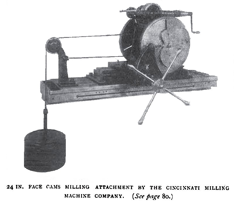 906 Cincinnati Milling Machine Co., 24 in. Face Cam Milling Attachment
|
|