|
Title: |
1848 Article - Description of the Daniels planer |
|
Source: |
Scientific American 4 November 1848, Vol. 4 No. 7, p. 52. |
|
Insert Date: |
10/24/2003 10:54:36 PM |
Article text:
DANIEL'S PLANING MACHINE.
Among the many Wood Planing Machines that have been invented and which are at present in use, no one is better adapted for some purposes, than the one which we have here represented in these two engravings. For wood that is somewhat rough, and when the work is not required to be exceedingly fine, perhaps it is the best machine in use, at any rate, it should never be absent from any small country saw mill where there is power to drive it, for certainly it will soon pay for itself, as it is exceedingly cheap, simple and strong, seldom needing repairs - the grand desideratum in all kinds of machines.
DESCRIPTION - Fig. 1, is a perspective and fig. 2, a top, or view of the machine looking down upon it. The same letters indicate like parts on both engravings. A, represents the frame. B B, is the moveable bed plate, C C, are transverse under bars. D D, is an iron rail on the upper surface of A, and there is a small groove in the transverse bars to slide on the rail as the bed is carried backwards and forwards. E E, are lappets to wedge in, by turning them up and slacken the board by turning them down. F F, is the revolving cutter arm or stock, fig. 2, and G G, are the cutter knives or gauges on the extremities of said arm. TI, is a disc which is secured to the frame so as just to allow the board to pass under it, yet to exert a pressure on the board so as to let the whole face of it, however warped, be subjected equally to the action of the cutters, which plane by their rotary motion at the outside of this disc. J, is a heavy roller suspended op the frame and pressing on the board to graduate or smooth the towards the cutter. I, fig. 2, is a board in the act of being planed. S is the main driving band and L is a pulley on a vertical shaft behind the upright post. N, is a vertical shaft on this side of the machine.
On the lower ends of these two shafts are pulleys which by bands move small stub shafts with pinions under the moveable bed B, - the pinions meshing into the rack and carrying backwards and forwards the bed with the board to and from the cutters. The reverse motion is given by the handle M, carrying the bed or table, as it is sometimes called, to and from the revolving cutters. The motion is changed by the lever of M, which moves a clutch in the usual way. K, is a pulley on the driving shaft, which by a band passing around R, as seen in fig. 2, drives the cutter shaft.
The operation of this planing machine is so simple, that every one who reads this description will understand it, and although it has been patented some time, yet an understanding of its construction and operation will no doubt be of interest to many.
We have now on hand one of these machines which we will dispose of for the very low sum of $250. It is capable of planing boards, timber, or any stuff from one fourth to 16 inches thick, by 1 to 22 inches wide and 16 feet long. It is so simple as to be easily managed by a boy, and operates with great rapidity and beauty. Any number of pieces of different thicknesses or lengths, can all be planed down even at one operation. It performs a day's labor of one man in 20 minutes.
We can ship it to any part of the country with perfect safety. Letters may be directed (post paid) to Muon & Co., Scientific American Office, New York. |
|
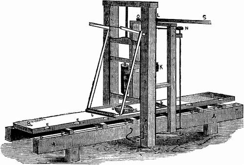 Figure 1
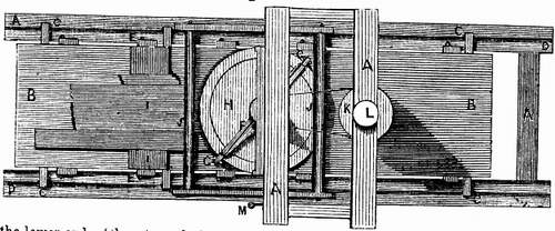 Figure 2
|
|