|
Title: |
1868 Article-E. P. Rider, Foot-Powered Woodturning Lathe |
|
Source: |
Scientific American 23 Dec 1868 pg 406 |
|
Insert Date: |
5/7/2012 10:03:32 AM |
Improved Lathe for Dentists, Model Makers, etc.
Dentists, amateurs, and others who use the foot lathe, experience more or less annoyance from their inability to stop the head spindle suddenly, the momentum of the fly wheel being difficult to overcome. This entails a great loss of time, particularly if the work is to be examined frequently. The lathe herewith represented is intended to obviate these objections.
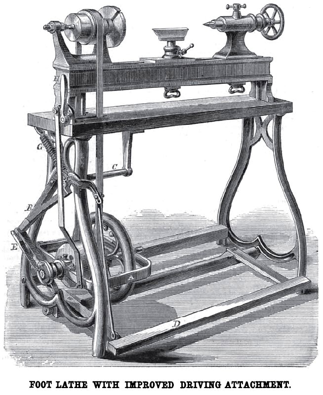
The driving shaft, carrying the cone pulleys and a small flywheel, is mounted in a frame. A, under the headstock of the lathe, and is pivoted on stands secured to the rear bar of the lathe, so that the frame, with shaft and wheels, may be raised or lowered to a certain extent.
The wheel shaft projects beyond the end of the lathe, and carries a fixed ratchet wheel at the extreme end. Between the ratchet and the box of the shaft is a flanged pulley, turning loosely on the shaft, sufficiently wide to receive two narrow belts side by side. One of these is attached to the long arm of a pendulum lever, B, the shaft, C, being its fulcrum. To the other, or short arm of the lever, is pivoted the rod that connects with the treadle at D. Another narrow belt, which the flanged pulley receives, is fastened at one end to a guide bar or bow, E, pivoted to the long or lower arm of the lever, B. The other end of both these belts is secured to the face of the loose flanged pulley, in such a manner that when one is wound on the pulley the other is unwound, as when the foot of the lever is furthest from the shaft the strap secured to B is run out, while that secured to E is wound up. A spring, G, balances the weight of the treadle and its appurtenances. A pawl and light spring on the outer head of the flanged pulley serves to makes connection between the loose pulley and shaft by means of the ratchet. A bell-crank lever at H connects by a rod with the pivoted frame, A, by which the frame can be raised to slacken the belt, or lowered to tighten it. When raised, the driving belt will be slackened, so that the spindle may be instantly stopped. The treadle stops as soon as the foot is removed, and always at the highest point, while the driving shaft continues to revolve. It is evident that a very high speed maybe obtained by this contrivance, while the stroke of the operator's foot may be of any limit required.
E. P. Rider, 230 Center Street, New York city, manufactures these lathes largely to order for model makers, mathematical instrument makers, watchmakers, etc.
Patent # 53,046 |
|
 1868 E. P. Rider, Foot-Powered Woodturning Lathe
|
|