|
Title: |
1869 Article-James M. Bryan, Tire Bender & Punch |
|
Source: |
Scientific American 09 Dec 1868 pg 376 |
|
Insert Date: |
5/4/2012 9:58:43 PM |
Improved Tire-Bending and Punching Machine
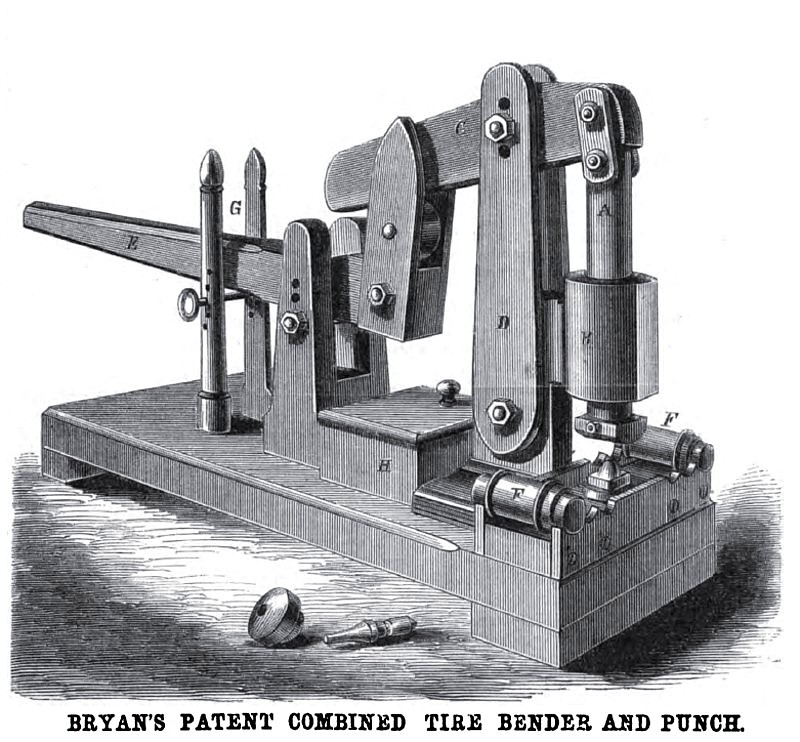
The objects of this machine are to bend either light or heavy iron when cold, to bend it to any given diameter or radius, and to punch cold iron, the machine being operated wholly by hand. It is a common adaptation of the lever so arranged in its parts as to yield great power.
The plunger, A, works vertically in a head, B, and its upper end is connected to the lever, C, by toggles, the lever being suspended between the upright pivoted ears, D. A hand lever, E, carries a roller on its inner end, as seen, upon which the long arm of C, rests and by which it and the plunger is operated. For bending tires or iron bars for any purpose the cylindrical formers, P, are placed in bearings on the rest, and a die, having a set screw in its top with convex head, is dropped into a hole directly under the plunger. A. Then, for bending tires, a pattern, termed by wheelwrights a "follow pattern," of the curvature of the tire to be bent, is placed upon the formers, F, with convex edge; downward ; the set screw in the die is then turned to touch the under edge of the pattern, and the plunger with its rounding head is brought down toward the set screw, having a space between of the thickness of the iron to be bent, the descent of the plunger being governed by a pin passed through the guides, G, for the hand lever to strike upon when brought down. The set screw gage may now be removed and the machine is ready.
The formers, F, have on one end a fixed flange and on the other an adjustable one, to guide the iron bar or tire on a straight line in passing under the plunger. The inventor says that one man of ordinary weight can bend, by means of this leverage, tires four inches by one inch, or three by one and a half inches, when cold, while another person guides the tire bar. In punching, dies and punches of any form may be used, the die fitting in a hole under the plunger and the punch in a hole in the plunger and held by a set screw. Specimens of the punch and die are shown in the engraving on the floor. The box, H, on the platform of the machine is a receptacle for the dies, punches, gages, etc.
Patented June 2, 1868, by James M. Bryan, who may be addressed for State, county, manufacturing, or shop rights, at Penningtonville, Chester county, Penn.
Patent # 78,420 |
|
 1869 James M. Bryan, Tire Bender & Punch
|
|