|
Title: |
1868 Article-N. C. Stiles & Co., Punching Press |
|
Source: |
Scientific American 04 Nov 1868 pg 296 |
|
Insert Date: |
5/3/2012 7:45:54 PM |
Improvement in Power Punching Presses
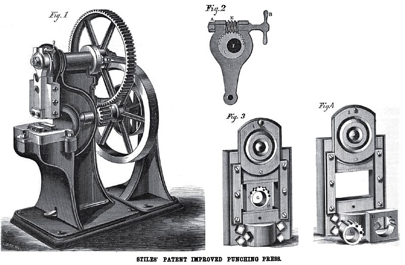
Twenty years ago the punching press existed only in a very crude form, and was used but seldom, and then only for a special class of work. Now it is an elaborate and workmanlike machine, one of the most valuable tools the machinist uses, and is applied to many purposes. Small forgings are finished by it, and their substance condensed and surfaces smoothed, while its power of rapidly cutting out and fashioning blanks of almost all forms, has scarcely a limit.
Fig. 1 is a perspective view of a powerful back geared machine. The pitman on the front connects at one end with the sliding block, or punch stock, and at the other end with a toothed eccentric on the main shaft, the teeth being cut around a portion of its periphery. These teeth engage with a worm turned by a hand lever, the devise being in section in Fig. 2. By this means the stroke of the punch may be graduated, and governed to the minutest fraction of an inch.
Figs. 3 and 4 represent the Stiles' patented device for graduating the stroke of ordinary crank presses, by which means the stroke may he graduated to the sixty-fourth part of an inch. The eccentric marked (J has a series of semicircular holes on its periphery, engaging, when in position with similar holes in the block, H, the eccentric being moved on the shaft by means of a pronged wrench fitting the holes seen on its face, and being held in connection with the block by a pin fitting the two semicircular engaging apertures. In Fig. 3 the eccentric is seen seated in the block, and in Fig. 4 both the eccentric and block are seen removed. The face plate, or cover, I, in either case is raised.
This device is the principle, and one of its adaptations to the adjustment of the stroke of the punch, the toothed eccentric, however, in Fig. 2 is an improvement on the original design, which was described and illustrated on page 305, Vol. X., current series of Scientific American.
In Fig. 2, A is a tightening nut on the end of the worm shaft, the shaft being worked by the handle, B, by which the eccentric, C, is turned on the shaft, F, thus governing the stroke of the pitman, D, and the consequent throw of the punch stock. E is the worm meshing with the teeth on the eccentric.
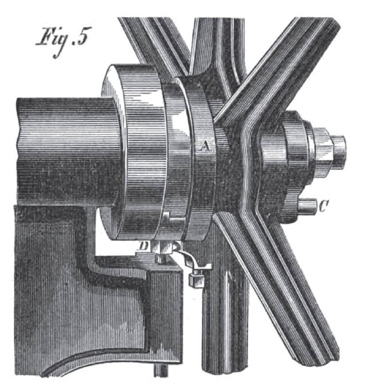
Fig. 5 is a perspective view of the parts of the machine containing the stop or lock motion, and Fig 6 is a vertical longitudinal section of the same. In both figures the same letters of reference are used. A is the hub of the driving wheel, turning free on the shaft, B, and locked or keyed to the shaft by the spring bolt, C, which is held by means of the vertical catch, D, the top or head of which is crescent shaped, its inner surface fitting the shaft, and its reduced end edge allowing the end of the bolt, C, to pass between it and the shaft or outside, as the position of the catch, D, may determine, which position is governed by the action of the treadle seen in Fig. 1, and operated by the foot of the workman. Spiral springs on bolt, C, and catch, D, assist in the operation of the stop motion. So long as the workman presses upon the treadle, the bolt keeps the driving wheel in connection with the shaft, and the punch is operated, but when he releases the pressure of his foot the catch, D, is forced upward by its spring, and the bolt or key, C, engages with the other surface of the head of D, and releases the key holt, leaving the driving wheel to revolve freely on its shaft without imparting motion to the punch. The relation of the punch and the key bolt is arranged so that the punch must stop always at the highest point of its stroke, so there can be no chance of cutting off fingers by the continued action of the press after the treadle and its connections have been put in operation.
This machine and its parts are the subject of several patents, procured through the Scientific American Patent Agency, dated January 26, 1864 ; January 30, 1866; re-issued December 26, 1865, and April 2, 1867, Manufactured by N. C. Stiles, who may be addressed at Middletown, Conn.
Patent #s 41403, 52,335, RE 2,139 & RE 2542. |
|
 1868 Article-N. C. Stiles & Co., Punching Press
 1868 N. C. Stiles & Co., Punching Press Detail
 1868 N. C. Stiles & Co., Punching Press Section
|
|