|
Title: |
1868 Article-Silver & Deming Manufacturing Co., Hub Boring Machine |
|
Source: |
Scientific American 21 Oct 1868 pg 264 |
|
Insert Date: |
5/2/2012 12:58:21 PM |
Improvement in Hand machines for Boring Wheel Hubs.
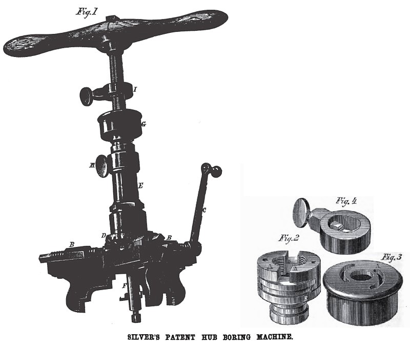
The large engraving is a perspective view of a self centering hub borer, which adjusts and holds the hub in position while being bored, and forms a square shoulder in the hub at the bottom of the bore. The chuck frame consists of three equidistant radial arms, having dovetailed slots in which slide the jaws, A, having corrugated grips or faces for engaging with the surface of the wheel hub, and holding it firmly. That portion of the jaw that projects above the radial arms is a nut, B, in which works a screw, the outer end of which is squared to receive a wrench, C, and the inner end carrying a beveled pinion engaging with a bevel gear turning loosely on the shank of the spider or jaw frame. By this means, whichever screw is turned, the two others, by the medium of the pinions on their ends, and the central gear, must have a common and simultaneous movement. Thus the jaws will be advanced to or receded from the center in perfect accord, and bring the center of the hub exactly coincident with the center of the machine.
That portion of the jaw chuck above the wheel, D, is screwed to a stock, E, both being hollow to receive a boring mandrel, P, carrying a cutter at its lower end. The upper portion of this mandrel is threaded with a screw of about ten to the inch, sufficient for ordinary feed for wood cutting, and has a handle similar to that of an auger. The feed nut, G, with which the mandrel thread engages is of peculiar construction. It is seen plainly in Fig. 2, the nut is in two halves, A, which slide in a dovetail slot cut across a circular bed piece, B. The whole is covered by the cap, Fig. 3, and the half nuts are moved to or from the screw by a pin or screw in each projecting into semi-spiral slots, A, in the top of the cap. Pins on t! e lower portion of this cap are seated into an annular channel on the boss of
B, Fig. 2, so that the cap may be turned without lifting from place. This combined nut and cap is held in place in the stock, E, when the machine is in use, by a thumb screw, H, Fig. 1, that fits in an annular groove on the shank of the circular bed piece or block, B, Fig. 2.
Fig. 4 is a gage for determining the depth of the hole to be bored; seen also at I, Fig. 1. It has an oblong hole, a portion of its interior being threaded to fit the screw of the mandrel; and on the opposite side is a gib, also threaded on its end, fitting in a chamber, and moved to place by a thumbscrew. These opposite threaded portions prevent injury to the screw of the mandrel when the gage is set up.
When a hub is to be bored, the gage is secured on the mandrel at a proper height above the cap of the feed nut, to bore the required depth of hole in the hub. The hub being held in the jaws, the mandrel is turned, the tool being fed by the feed nut at the top of the stock, E, until the gage comes in contact with the cap of the nut. The set screw, H, is then slightly loosened, which permits the feed nut to turn with the mandrel, and a few turns of the handle forms a perfectly square shoulder at the bottom of the hole. To withdraw the mandrel from the bored hub, it is only necessary to give the cap of the feed nut a slight turn to the left, separating the two halves of the nut, when tho mandrel can be lifted out.
Patented August 11, 1868, antedated July 25,1868, by A. R. Silver, assignor to himself and John Deming. Address Silver & Deming, Salem, Ohio.
Patent # 80,837 |
|
 1868 Silver & Deming Manufacturing Co., Hub Boring Machine
|
|