|
Title: |
1863 Article-Tuxford & Son, Portable Steam Engine (part 2) |
|
Source: |
The Practical Mechanic's Journal, 01 Mar 1863, pgs 314-317 |
|
Insert Date: |
4/5/2012 1:20:47 PM |
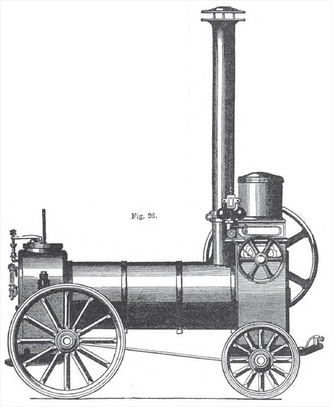
Next followed the detaching of the thrashing machine from the engine frame work, in consequence of the introduction of the combine it thrashing machines; and where the machine had stood was introduced a table engine with vertical cylinders; tubular boilers were introduced, and afterwards followed the patent housed engine, with vertical cylinder, and boilers with flues and tubes combined. At the Great Exhibition in 1851, this last kind of engine had a prize awarded to it; and the French Government obtained one for experiments in the Museum of Arts and Trades at Paris. The following illustrations, figs. 24 and 25, shows this engine in perspective and section elevation respectively. A modification of this engine was made afterwards by inverting the position of the cylinder; this arrangement is shown in fig. 26; the leading feature remains the same in both kinds of engines, viz., the vertical position of cylinder, and both kinds are in general demand. The consumption of fuel of the patent housed engine, in the trials of the Royal Agricultural Society at Carlisle, gave an economy that had never previously been attained with portable engines; with 14 lbs. of coal for each horse-power, the engine ran (or 3 hours and 47 minutes, doing full duty the whole of the time, and being at the rate of 3¾ lbs. of coal per horsepower per hour.
Referring to figs. 24 and 25, which represent a 10 horse power upright cylinder steeple engine, enclosed in an iron casing attached to the hack uptake of the boiler, which is made with parted flues and return tubes, it may here be remarked, that the vertical cylinder has an advantage over the horizontal arrangement, in the circumstance that the former is not liable to wear oval like the latter. This is a very good specimen of a steeple engine, all parts being strong and well proportioned; the steeple construction admits of a long connecting rod without great height. Fig. 25 is a longitudinal vertical section of this engine, upon a wooden frame and wheels, and shows the interior of boiler and arrangement of the engine attached. There is an objection to the way the feed pump is worked from one side of the cross-head, thus giving a slight side pull to the same.
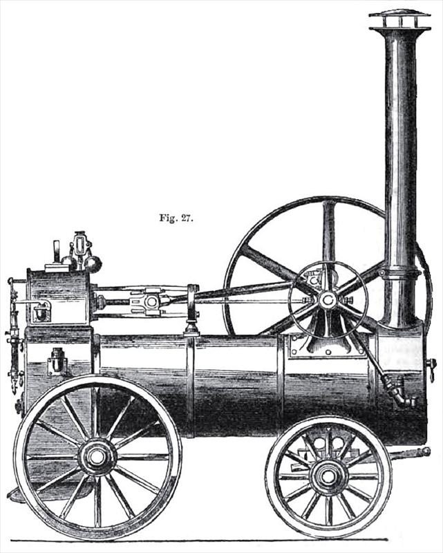
Fig. 27 shows the horizontal cylinder engine with tubular boiler in its most perfect form by the same makers. All stuffing boxes in Messrs. Tuxford & Sons' engines are of the neat and convenient form shown in half section and elevation in fig. 28. There are no counterweights on these engines. The boilers are all strongly stayed, and double felted and wood-lagged wherever it is practicable. The engines are supplied with expansion valve and steam-jacket at a slight extra charge; in that case the steam jacket is sup plied directly from the boiler, with a separate steam admission to slide jacket. The pump and valve box arrangement is such as to admit part of the feed water to be returned into the supplying tank or tub, thin enabling the pump to be always working, and pump barrel and valve box always full of water, besides heating the feed water.
The engine shown in fig. 26, is a very well designed engine also. The feed can be regulated from the outside of the housing. The guide blocks are, in this engine, also lined with brass, and adjustable. The boiler is of the common locomotive stamp. It may not be out of place here to mention the following. The combined boiler with flues and return tubes, as shown in section in fig. 25, is not liable to leakage at the tube ends as the common locomotive boilers. This is owing to the fact that the thick flue plates have not the same variations in contraction from the cold air rushing through them as the thin tubes have, when the furnace door is opened for putting fuel on the grate; and farther, the air becomes heated as it mixes with the flame, and when it arrives to the hack uptake to return through the tubes, it is hot and nearly combined with the gases, and thus the tubes have never any cold air through them, and are free from that extreme variation in contraction and expansion, which tends to produce leakage at the tube ends.
The common portable engine manufactured by this firm, and shown in fig. 27, is as good a sample of its class as ever turned out. The cylinder is steam jacketed; the guide bars are of steel, and the guide blocks have adjustable brass linings on both sides; the brasses in crank shaft bearings are adjustable sideways. In fig. 29 is a vertical section, showing the construction of a Collinge patent axle box, as applied to Messrs. Tuxford & Sons' portable engines. The oil dripping from the guides is used over again as the connecting rod dips into the oil collecting pan at each stroke. All the engines turned out by this firm are of superior material and workmanship.
The 8 horse power engine weighs 70 cwts., and, when fitted with steam jacket and expansion slide valve, (when will engineers cease to make the blunder of applying the latter, without, in that case, the unavoidably necessary adjunct of the former?) consume only 3½ lbs. of coal per horse power per hour. |
|
 1863 Tuxford & Son, Portable Steam Engine (section view)
 1863 Tuxford & Son, Portable Steam Engine
 1863 Tuxford & Son, Portable Steam Engine
|
|