|
Title: |
1860 Article-W. Manning & Co., Barrel Head Cutter |
|
Source: |
Scientific American 04 Feb 1860 pg 81 |
|
Insert Date: |
1/12/2012 7:22:51 PM |
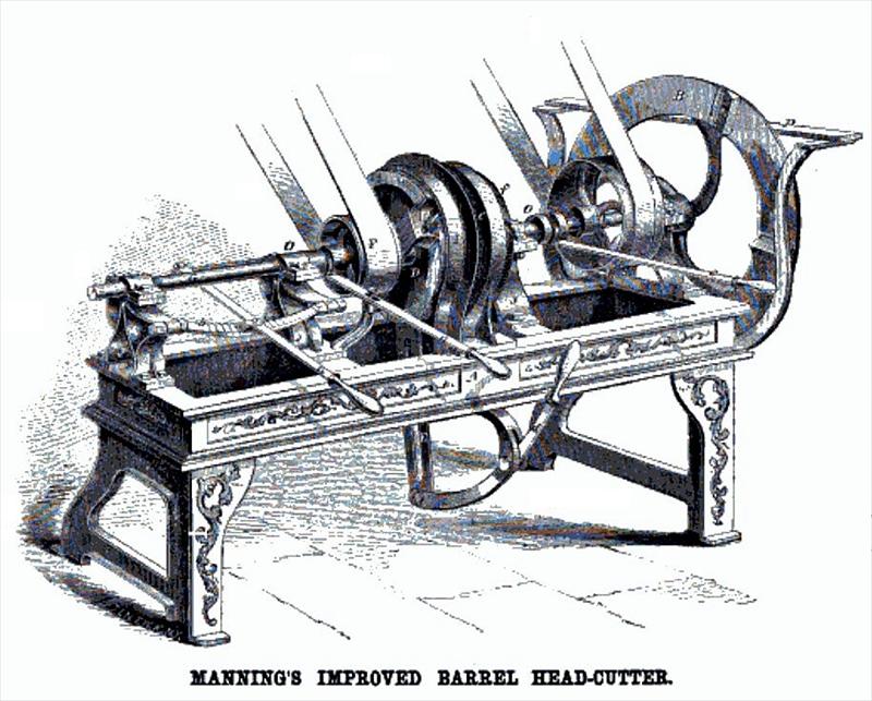
IMPROVED BARREL HEAD-CUTTER — The great number of patents, which we have taken out, within the last few years, for improvements in machinery for cutting barrel heads, illustrates in a striking manner the beauty of our patent system, and its inconceivable power in promoting the prosperity of the country. One person makes an invention of some machine—another examines it, and some improvement in it occurs to him; thus step by step it is brought more nearly to perfection by the action of numerous intellects. In barrel head-cutters, though it is difficult to conceive of a more simple and compact machine, or one which should operate more rapidly or produce more perfect work than the one illustrated in the beautiful engraving annexed, still we have seen so many things that seemed to be almost perfect very greatly improved, our experience would prevent us from being surprised if many applications should yet be made for patents for this class of machines. This invention is, however, one of the kind that we take especial pleasure in illustrating. It is made by a practical mechanic on sound common sense principles, and proves on trial to work with all the perfection that was expected of it.
The frame, A, that supports the machinery 19 made of cast iron, and is about six feet by two. Across the center of the frame is placed a cast iron plate, with a ring cast solid to it and rising up from the frame, as seen at I; the inner diameter of this ring is a trifle larger than the head to be made. On the frame are stands in which
are bearings, as seen at J J J J, for two shafts, G G, placed in line, so as to meet exactly in the center of the ring before mentioned. The shaft at the left has a lateral motion only, and slides back and forth through its hearings, and is held from turning by a feather; on the end of this shaft is placed a disk, D, of a less diameter than the annular plate or ring before mentioned; also between the disk and bearing is placed a hub, O, to which is attached a pulley, F, and also a ring, H, holding rotary cutters. The shaft at the right has a lateral as well as a rotary motion; between the bearings is placed the pulley, F, and on the inner end is placed another disk, f, that holds the cutting knives for planing the head, and cutting the bevel on one side. On the other end of this shaft is placed a wheel-jointer, B, that serves the double purpose of jointing the heading and acting as a fly-wheel; this jointer is held close up to the bearing of the shaft by means of a groove in the hub, and the shaft is allowed to work through it on a feather. The plate seen at E is a thin plate of wrought iron that slides up between the cutters through a slat in the center plate, and is operated by the handle, d.
Having thus described the several parts, it will readily be seen that the operation is extremely simple and expeditious.
The heads may be made of any number of pieces, and are first jointed by a boy, who can lay them down without moving from his position, within reach of the one who operates the machine, who has perfect control of every part without stepping from his place. He first takes the number of pieces for a head and places them in the machine, one upon the other, edgewise between the ring, I, and disk, D, and by means of the handle, a, to which is attached a ratchet and pawl, b, clamps the pieces firmly between the disk and ring; the handle, c, is then taken hold of, which brings the rotary disk, with
made—one at the last National Fair at Chicago, and the other at the last fair held at St. Louis by the Agricultural and Mechanical Institute, and at each it was awarded the first premium. One of these machines is now on exhibition at No. B3 Ann-street, this city.
The patent for this invention was issued, through the Scientific American Patent Agency, to Wilsie Manning, of Rouse's Point, N. Y., March 2, 1858, and persons desiring further information in relation to it will please address W. Manning & Co., Rochester, N. Y. — Patent # 19,509 |
|
 1860 W. Manning & Co., Barrel Head Cutter
|
|