|
Title: |
1892 Article-Bardons & Oliver, 14 inch Turret Lathe |
|
Source: |
American Machinist 18 Feb 1892 pgs 1 & 2 |
|
Insert Date: |
12/23/2011 7:20:38 PM |
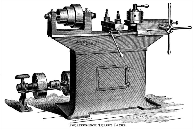
Fourteen-inch Turret Lathe.
We give on this page a general view, and on page 2 some details of construction of a new turret machine built by the new firm of Bardons & Oliver, of Cleveland, O., who have introduced some features worthy of attention.
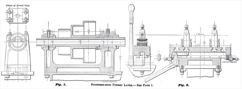
The hollow column has been adopted as the support of the bed, for the purpose of giving the utmost strength and rigidity, and within the column there are shelves for the reception of tools and fixtures which can thus be locked up, good locks being fitted to the door for this purpose. By reference to the section of the head-stock, Fig. 1, it will be seen that more than usual strength bus been secured here by making the uprights double or columnar, and greatly increasing their depth, besides which heavy sections of metal are employed.
It will be noticed also that the box is supported in the head practically its entire length, each end of the seat counter-bored for the reception of the flange on the box. This not only supports the box very solidly, but reduces to the smallest possible amount the overhang of the work beyond the box.
The thrust of the spindle is taken on the front of the main box, and lost motion is taken up by adjusting the collar at the rear of the same box, all expansion or contraction of the spindle affecting the position of the rear end only where provision is made for it, and it can do no harm. The main bearing, as shown by the drawing, is 2½"x3¾", and the cap is held in place by four bolts. The boxes are in halves and can be renewed, and the original alignment of spindle precisely restored by simply doing a good job of lathe work in making new ones.
Fig. 2 gives two sections of the tool, or cutting-off slide, with the manner of connecting to the lever and the arrangement of the stops, which are placed one in front and the ether at the rear with jam nuts outside, so that the stops are easily adjusted and are free from spring or any inclination to yield when pressure is brought upon them. The tool-posts are provided with threaded collars, by which the height of tools is easily regulated.
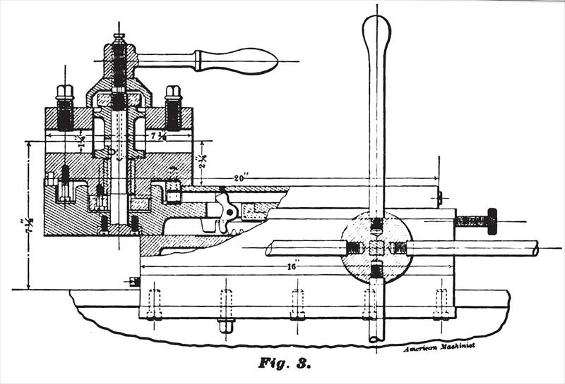
Fig. 3 is a view of the turret slide and block, with a vertical section of the turret showing the method of securing it to the slide. The turret revolves automatically, and is supported upon a bearing which is of hardened and ground steel. There are six holes, 1¼" diameter. The length that can be milled by the turret tools is 6½". At each side of the turret slide there is a taper gib which extends the entire length of the slide, and can be adjusted by the screw at the rear. By this adjustment all side wear of the slide can be readily taken up and the alignment preserved. The turnstile is fitted to the pinion shaft upon a square section, which precludes the possibility of its becoming loose, even with the most severe usage. A speed of the countershaft of 350 revolutions gives for the spindle, speeds of 565, 850 and 316 revolutions. The machine weighs, ready for shipment, about 1,300 pounds. |
|
 1892 Bardons & Oliver, 14 inch Turret Lathe
 1892 Bardons & Oliver, 14 inch Turret
 1892 Bardons & Oliver, 14 inch Turret Lathe Parts
|
|