Image
Manufactured By:
J. A. Fay & Co.
Keene, NH; South Keene, NH; Worcester, MA; Norwich, CT; Cincinnati, OH
|
|
|
Title: |
1895 Article-J. A. Fay & Co., Wood Planers |
|
Source: |
Modern Mechanism 1895 pgs 628-630 |
|
Insert Date: |
12/4/2011 12:50:13 PM |
The Modern Daniells planer is built entirely of iron and steel, except the face of the table, which is made of yellow pine. This gives the machine great strength, and especially adapts it to the use of railway, bridge, and car builders, who require to take large lumber or timber cut out of wind or to reduce it to square dimensions. As made by J. A. Fay & Co., the iron frame machine. Fig. 1 has its sides cast in sections, according to the length of machine wanted. The ways, on which the table moves are cast with the sides and planed to fit the slides of the table, which are continuous, and form a good bearing at all points. The table is made to travel in either direction under the cutters by a self-acting motion, and it will plane forwards and backwards. The carriage has a dog or tail-screw let into the back end of the platen, so as to come below the surface, and is operated by a crank wheel. The main spindle is properly of steel, of large diameter, and running in long bearings; the arm should be. of wrought or malleable iron. The material is held down by dead weights or guide plates. The carriage has side clamps for edging up. The levers for starting, reversing, or stopping the motion of the table, with the hand wheel for raising and lowering the cutters, are all within easy reach of the operator, and the table can be moved by a hand wheel when the machine is not in operation. The feed works have three changes of feed, admitting of planing while the table moves in either direction. The rack being beneath the table, with a vertical pinion, there is no danger of lodging of shavings, nor tendency to raise the table by the force required to move it. The main driving belt is not a quarter-twist, as in the old makes; the countershaft being attached over the machine to the building and parallel to the main shaft, thus giving a straight belt; and the driving belt for the cutter head acts at a right angle to the countershaft. This does away with the old vertical countershaft, and the annoyance of quarter-twist belts, and the tendency of the main belt to draw the machine out of line.
A machine by the same makers, which is a combination of the Daniells and the Woodworth planing machines, is of great utility. It is shown in Fig. 2. There is a wooden frame with iron housings or uprights for carrying the cylinder and frame. The planing cylinder is horizontal, and lipped with steel, carrying three knives and running in long bearings. It is supported in its frame upon two heavy iron standards having planed surfaces, upon which it is gibbed and moved vertically, and at an angle, to retain the driving belts at the same tension. There are on each side of the cylinder adjustable pressure rollers to hold the lumber firmly to the platen; these rollers also being arranged that they may be lifted up so that there will be no pressure when planing dimension stuff or taking lumber out of wind. The feed rollers when not in use may be moved out of the way on planed slides. They are connected by expansion gearing, and will take in lumber up to 4 in. thick. When used for surface planing the table is placed with its end under the cylinder and pressure rollers, and the feed rollers moved into position. The platen or carriage for using the machine as a Daniells planer has friction feed works, with changes of speed, and is arranged to plane while the carriage is running in either direction. The vertical adjustment of the cutting cylinder is sufficient to allow stuff up to 24 in. thick to be dressed. It will be observed that the feature of the Daniells planer which is retained is the moving carriage or platen; the cutting being done by the knives upon the horizontal rotating cylinder, whether the feed be by rollers or by carriage. A modification of this machine dispenses with the feed rollers, but retains the pressure rollers each side of the knife cylinder; although provision is made for the application of power-driven feed rollers, with expansion gear—and in this case the carriage remains stationary. The machine is rapidly changeable from a dimension machine to a wide surface planer.
The special peculiarity of this class of machine is that it will make a surface good enough for glue-jointing, while it will plane in either direction of the carriage, thus greatly adding to its capacity.
In some timber planers the cylinder, instead of the bed is raised and lowered, so that a train of rolls in stationary stands may be placed at each end of the machine; and the top of these timber rolls being but a trifle lower than the travelling bed, will support long sticks while being fed through the machine. This also does away with the annoyance and delay of adjusting the timber rolls every time the size to be planed is changed. |
|
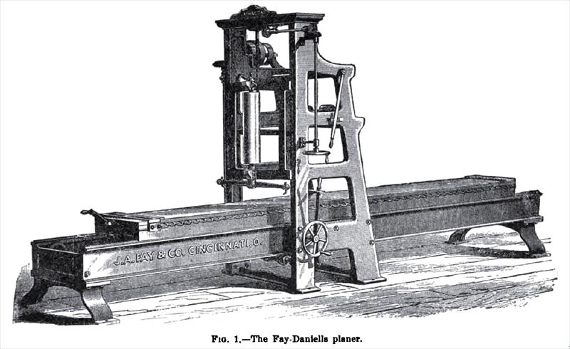 1895 J. A. Fay & Co., Fay-Daniells Wood Planer
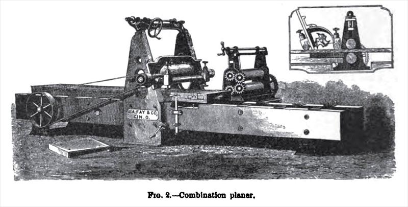 1895 J. A. Fay & Co., Combination Wood Planer
|
|
|
|