|
Title: |
1895 Article-Detrick & Harvey Machine Co., Open-Sided Extension Planer |
|
Source: |
Modern Mechanism 1895 pgs 624-625 |
|
Insert Date: |
11/28/2011 8:28:06 PM |
|
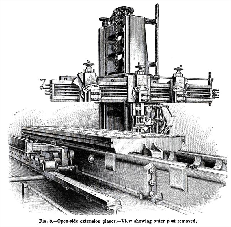
The open-side planer is in no sense a "special" tool, as it does the same work as the ordinary two post planers of equivalent size. A comparatively 8 m a 11 "open-side" tool will, however, plane work which would necessitate a larger planer of the regular style. To drive these planers, the builders use the Sellers' spiral planer motion. The cross beam is supported by a brace rigidly bolted to back of post. This post is well and heavily proportioned, and is amply strong to overcome any strain. The post takes a bearing on the bed equal in length to 1½ times the amount of overhang of beam. The head on the beam has automatic feeds in all directions. The beam and cross rail are raised and lowered by power. The builders claim that there is less vibration at end of the beam of this machine than there is in centre of the beam of a two-post planer. The Open-side Extension Planer, built by the Detrick & Harvey Machine Co., is shown in Pig. 8. This style of planer differs from the standard open-side planer in that it has an outside post and long beam. This post is adjustable on an extension bed to and from the platen. Both side heads can be used simultaneously on a wide range of work varying in width, while the long beam gives a corresponding range of travel to the horizontal heads. If it is desired to use the machine for work which will not pass between the posts at their extreme limit, the outer post may be entirely removed, and by running the beam back in its housing, the tool is converted into a standard open-side planer, as represented. The general design of extension planer is similar to the standard open-side machine, except that certain parts are made heavier to meet the increased capacity, and to accomplish the additional work, which it may be called upon to perform. With these planers can be furnished an attachment designed for planing segments. In this case the beam heads are removed and placed on arms, which are swiveled from main saddles to side saddles. The heads with automatic feed can then be used for planing angles on segments. When once set at desired angle, any number of segments can be planed uniformly and accurately. A centre head on the beam may be used simultaneously with above to face off the joints of the segments. The Iron Age of J uly 16,1891, describes one of these planers built for the Walker Manufacturing Co., of Cleveland, 0., for planing the segments of large pulleys and sheaves (its size being such that all the segments, even of the largest wheels, can be planed at one setting), as follows: "The machine will plane 120 in. wide, 96 in. high, and 25 ft. long. Combined with great capacity and ability to do work 10 ft. wide, the tool is adapted to perform work of half that width as economically as a 60-in. planer. The planer is triple geared, which reinforces the already powerful spiral gearing, and makes the tool capable of taking several heavy cuts simultaneously. The width of the table is 60 in., and depth of the same through the Vs 14 in. Hearing on the V-ways each side is 11 in. The depth of bed, 24 in. The worm has an axial pitch of 10 in., is 16 in. long, and engages in a rack having a width of 9 in., and 21 in. pitch. The cross heads each have an 18-in. bearing on the beam, and the side heads a 15-in. bearing. The vertical travel of the main head is 14 in., while that of the side heads is 9 in. The bevel driving gear and pinion have a 7-in. face and lj-in. pitch. The weight is 140.000 lbs." |
|
 1895 Detrick & Harvey Machine Co., Open-Sided Extension Planer
|
|