|
Title: |
1895 Article-William Sellers & Co., Spiral-Gear Planing Machine |
|
Source: |
Modern Mechanism 1895 pg 623 |
|
Insert Date: |
11/28/2011 1:41:15 PM |
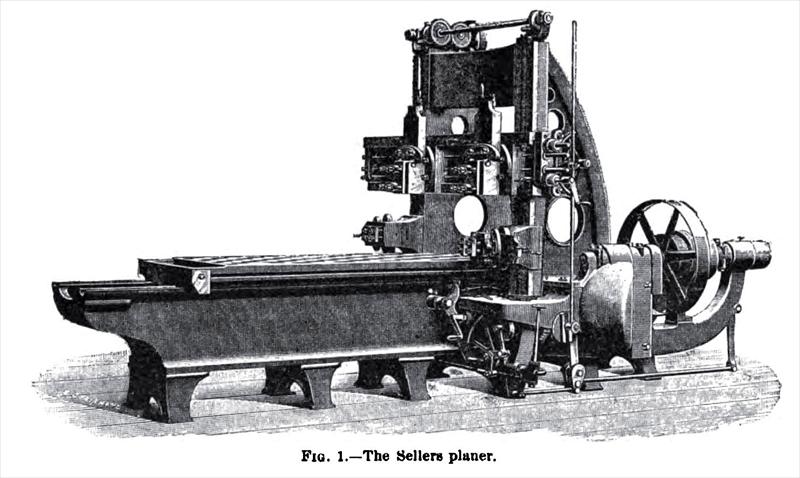
The Sellers Spiral-gear Planing Machine — At the Paris Exhibition of 1889) Messrs. William Sellers and Co., Incorporated, of Philadelphia, exhibited a planing machine, Fig. 1, which attracted great attention on account of the many interesting features which it possessed. For some years it had been tried experimentally in the works of the makers, but this was the first time that such a machine had been shown in public. The problem which the inventors, Mr. William Sellers and Mr. John Sellers Bancroft, had set themselves to solve, was to design a planing machine which would turn out work without any evidence of jarring or "chattering," so that it could be used without scraping or polishing, and yet present a good surface. In other words, they sought to give planed surfaces as good a finish as those from the lathe. They had also other subsidiary objects. Among these was the attainment of a greatly increased rate of travel on the back or idle cut; the ability to render the table self-stopping at the end of its stroke; to provide means for controlling the direction of the table movement and the operation of the feeds upon both sides of the machine ; to effect the operation of the feeding and tool-lifting devices at a uniform speed, whether the table was moving in on« direction or the other, and while the table was at rest.
To prevent a chattering motion being given to the table, the use of ordinary spur and bevel wheels, gearing into each other, is abandoned altogether. In place of them there are used pinions having the contact surfaces of their teeth arranged spirally around the axis. One such pinion gears with a straight-toothed rack on the table, its axis being inclined to the axis of the table at the necessary angle, while another on the pulley shaft gears with a straight-toothed wheel on the axis of the first pinion. The angles of the teeth of the pinions are such that the pulley shaft lies parallel with the table. By means of this system of gearing motion is communicated to the table without shock or jar, and the production of chatters is avoided. To gain a greatly increased rate of travel on the back cut, as compared with the forward cut (in the machine illustrated it was 8 to 1), the part subject to reversal at high speed is kept as light as possible. The pulleys run always in the same direction, the reversal being effected by a clutch between them, which engages alternately with each. The table, thie pinion shaft, and the clutch shaft are the parts which suffer reversal ; the first two move at comparatively slow speeds, while the latter is kept as light as possible, and special means aro provided for absorbing its momentum. When the table strikes the slop at the end of its stroke, it draws the clutch out of engagement with one pulley, and presses it lightly against the other, which is, of course, running in the opposite direction. In this way the pulley and pinion shafts are quickly checked, and the table moves forward, in relation to them, no far as to take up the backlash of the teeth, with the result that when the pulley shaft is reversed there is no jar. The reversal of the pulley shaft is not directly effected by the contact of the steps on the table with the tappet levers. All that is done by them is, first, to knock off the driving power, and to apply the brake. and simultaneously to set in gear an escapement motion by which certain wheels and a cam are made to give a semi-revolution and nothing more. The cam compresses a spring which bears on the reversing clutch, and forces it to engage firmly with the pulley against which it has been running in light frictional contact; the wheels put on the various feeds, which thus occur between the end of one stroke and the commencement of the next. By an ingenious device on the hand lever at each side of the machine, the escapement motion can be thrown out of action, and then, when the stops meet the tappet levers, the machine stops, and no feed takes place. At the Paris Exhibition, 1889, the machine was run at 18 ft. a minute for cutting, and 144 ft. a minute on the return stroke. |
|
 1895 William Sellers & Co., Spiral-Gear Planing Machine
|
|