|
Title: |
1909 Article-Reliance Electric & Engineering Co., Lincoln Electric Motor |
|
Source: |
Cyclopedia of Applied Electricity, 1909 pgs 439-442 |
|
Insert Date: |
11/10/2011 8:21:06 PM |
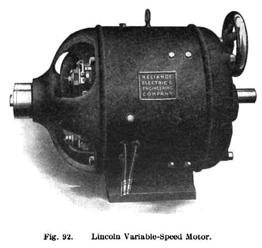
The Reliance Electric & Engineering Co. — This, concern manufactures the Lincoln direct-current motor shown in Fig. 92. These machines belong to the adjustable-speed class and are built in sizes ranging from ¼ to 30 H. P., and with speed variations as great as ten to one and as small as one desires. It is a simple shunt-wound machine, obtaining its speed variation by altering the magnetic circuit of the machine so as to weaken or strengthen the magnetic field.
The principal parts of this machine are shown in detail in Fig. 93, a portion of the illustration being in section. The end of the armature shaft on which the commutator is mounted revolves in a sleeve that slides in the journal bracket. This sleeve is moved back and forth by means of a forked lever controlled through a rod and nut, by the screw on the spindle of the hand wheel. The helical compression spring surrounding the lever rod always balances the
magnetic pull that is exerted by the poles on the armature core. The armature core is slightly tapered, the commutator end being larger in diameter than the other end and the pole faces are bored to the same taper. When the armature is drawn towards the journal bracket on the commutator end, the air gaps are increased in length and decreased in area. This increases the reluctance, thereby weakening the field and thus increasing the speed.
Sparking at the brushes when operating at weak fields is prevented by means of special commutating poles midway between the main poles. These commutating poles are in series connection with the armature and laterally displaced from the main poles on the side toward which the armature is withdrawn. The machine is so designed as to give sparkless commutation at all loads at any speed in either direction. The brush rigging is mounted on the end of the sleeve containing the ball bearing and therefore this bearing, brush rigging, and armature move in unison with no lateral displacement of the brushes on the commutator. The driving end of the shaft slides in a sleeve that revolves with it but does not slide endwise; the driving gear, coupling, or pulley is mounted on the end of this sleeve. |
|
 1909 Reliance Electric & Engineering Co., Lincoln Electric Motor
 1909 Reliance Electric & Engineering Co., Lincoln Electric Motor Cross-Section
|
|