|
Title: |
1900 Article-Fellows Gear Shaper Co., 36 inch Gear Shaper |
|
Source: |
The Journal of Railway Appliances, Feb 1900 pg 391 |
|
Insert Date: |
10/21/2011 1:08:46 PM |
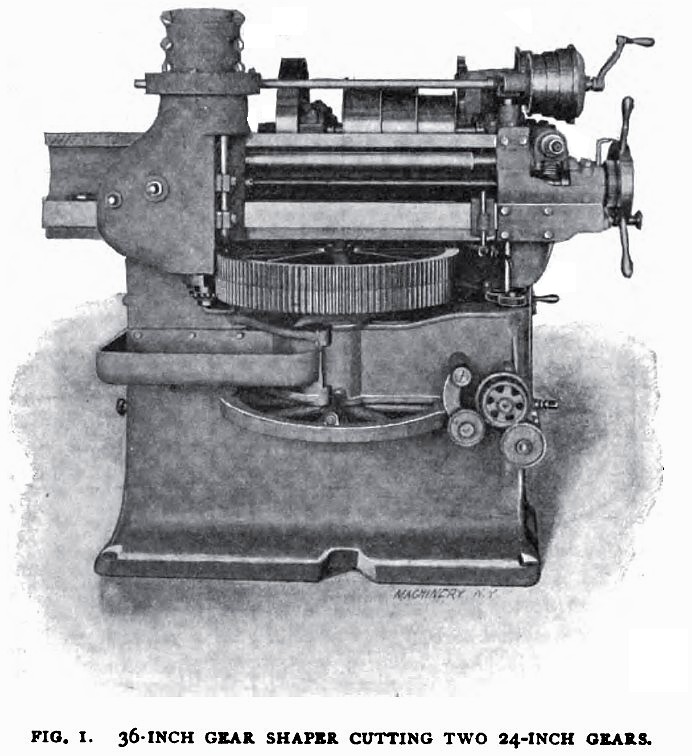
GEAR SHAPER IMPROVEMENTS — In the January, 1898, number of this paper was published a detailed description of the Fellows gear shaper, which embodied radically new principles for a gear cutting machine. The teeth of the gears are cut in this machine by a planing tool, instead of a milling cutter, and the tool that is used is nothing more or less than an accurately formed gear wheel of tool steel, having the sides and faces of the teeth so shaped as to form cutting edges, like the edges of a planer tool. This cutter, besides having a reciprocating motion across the face of the gear blank to be cut, revolves in harmony with the blank, just as a gear wheel and pinion would revolve when their teeth are in contact, and correctly-shaped teeth are gradually formed around the whole circumference of the blank. Only one cutter is required for gears of the same pitch of any size, and the principle of the machine is based or. the fact that a gear tooth can be made to form its conjugate in a blank running in correct relations with the tooth. This is an old principle, but it has been worked out in a very modern way in this machine.
By comparing the illustration of the Fellows gear shaper which we show herewith with that in the number of the paper referred to, it will be observed that several essential changes have been made in the design of the machine, as suggested by the experience gained with the original design during the past two years. It has been desirable to cut coarser pitches than was originally intended and this requires cutters of larger diameter than were formerly used. To accomplish the heavier work successfully, it is quite essential that the ram carrying the cutter be supported, if possible, the entire length of the stroke. The ordinary design, with overhanging ram, will not do. Also, an ordinary slide, large enough to support the cutter for most of its travel, would be excessively heavy. The problem was finally solved by giving the ram a circular form somewhat larger than the diameter of the largest cutter, allowing the cutter to follow the ram into its guide. Referring to the illustration, it will be seen that there are a pair of gear blanks in position, with the cutter operating: upon them. Above these blanks are the ways, or the cross-rail upon which slides the saddle carrying the cutter bar or ram. This ram is vertical and its lower end, with the cutter, can be seen at the left, projecting a short distance below the lower edge of the saddle. Another improvement that has been made is in the means used to control the cutter spindle. As stated above, both the cutter and the blank must rotate in unison and the cutter in addition has a reciprocating motion in order to cut the teeth. This double motion of the cutter is arranged by attaching the cutter to a spindle which passes vertically through the center of the ram and reciprocates with it, but which is free to turn inside of the ram so as to give the cutter the proper rotary motion. The latter motion is obtained through the medium of a worm and worm-wheel and the improvement consists in arranging the sliding connection between the worm-wheel and the cutter spindle so that there will be no backlash between the two, even after long wear. The way the problem is worked out is shown in Fig. 2. The cutter spindle extends above the cutter ram and a section at this point is shown in this figure. S is the cutter spindle and to it is keyed securely a piece of the shape shown at G, which moves up and down with the spindle. W is the worm-wheel, which has a long hub H extending upward for some distance. One-half of this hub is cut away and to it is bolted a cap, C, which has lugs L, L, extending inward and bearing on two flat surfaces of the guide G. Now, as the worm-wheel revolves, motion is transmitted to the spindle through its hub and the guide G, and, at the same time, the spindle and its guide are free to slide inside of this hub, and the sliding surfaces are at so great a distance from the center of the spindle, and are so well proportioned, that they are very durable. Moreover, after long wear any lost motion can be taken up by means of the cap. It will be noted from the photograph that the saddle has most of its bearing for the ram on the right side of the cutter, removed to give room to cut pinions with long hubs or quills. Fig. 3 shows the method of cutting the back gear quill of a lathe head and in Fig. 4 is an illustration of a method of cutting internal gears, work for which this machine is particularly adapted. The gear shown is the back-gear used on the Fellows gear shaper, which has an internal and an external gear on one hub. This gear is cut at one setting by the same cutter, the position of the cutter for the external gear being indicated by the dotted lines. |
|
 1900 Fellows Gear Shaper Co., 36 inch Gear Shaper
|
|