|
Title: |
1895 Article-Sprague Electric Railway & Motor Co., Electric Motor |
|
Source: |
Modern Mechanism 1895 pg 548 |
|
Insert Date: |
9/14/2011 12:23:22 PM |
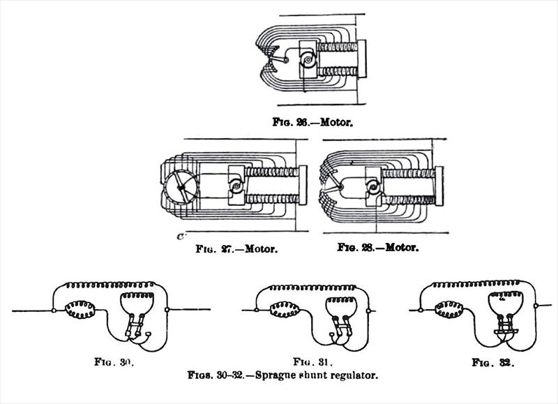
At the Philadelphia Electrical Exhibition in 1884. Mr. Frank J. Sprague made the first public exhibition of several of his motors, which were run on a constant-potential circuit. The Sprague motors may be divided into two classes, with subdivisions as follows: 1. Variable-speed Machines, comprising, (a) variable shunt; (b) Wheatstone bridge; (c) standard railroad. 2. Constant-speed Machines, comprising, (d) variable shunt; (e) long shunt; (f) short shunt; (g) combined shunts; (h) distorted windings. The above are for operation on constant-potential circuits, to which class of work Mr. Sprague has mostly confined himself. There are a number of other forms for both constant-potential and constant-current circuits, particular description of which is unnecessary here. In the variable-speed machines the object sought is, without introducing resistances external to the machine, to vary the potential differences existing at the armature terminals in a progressive manner from the maximum existing to zero; to reverse the potential without breaking the continuity of the field or armature circuits; to vary gradually the rotary effort of the armature, and, if necessary, also the strength of the field magnets. In a general way these results are accomplished by winding the field magnets in sections of variable cross-section and resistance, and arranging the armature circuit so that a greater or less number of the field-coil sections may be shunted to or put in series with it. In the simplest form (Fig. 26) one end of the armature circuit is connected with a contact arm arranged to travel over a series of contact blocks connected with different sections of the field coils, and the other end of the armature circuit is connected with one end of the series at its junction with the supplying circuit; as the arm moves over the successive contacts, the armature is shunted around a greater or less number of the sections of feed coils, and the difference of potential between the terminals of the armature circuit is varied from the maximum to zero. This method has been used to a considerable extent in introducing constant-speed machines into circuit without the use of a rheostat in the armature circuit. In another form (Fig. 27) each terminal of the armature circuit is connected to a movable arm, both arms being made to travel along the contact blocks in opposite directions, so that the difference of potential at the brush terminals can be made to vary from the maximum to nothing, and then reversed, thus going through the full range of maximum difference in potential in one direction to the maximum in the other. In the third form (Fig. 28) there are two series of field-coil sections, the bights being brought to two sets of contact blocks ; the armature terminals are
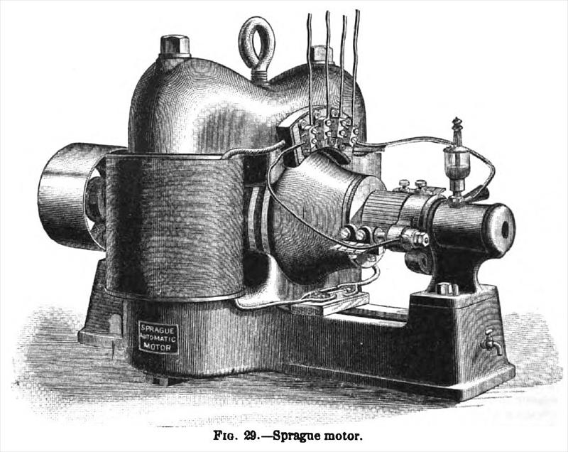
here also joined to two arms made to travel upon these contact blocks, so that the difference of potential at the armature circuit increases from zero to the maximum in either direction as required. In the standard street-railroad machine, the field magnets are wound with throe sets of field coils of variable cross-section and resistances, which are in series with the armature. These coils are varied in relation from three in series to three in parallel, thus changing the total resistance of the machine, and varying the torsional effort and speed with any given current. For more detailed description of this method, see Electric Railways, Sprague system. With the exception of this railway motor, the best known of the Sprague motors is that adapted to run at a constant speed on a constant-potential circuit under varying load, and for a time this was the only machine which had this quality. This machine is illustrated in Fig. 29. The method of regulating these machines was based upon the apparently paradoxical statement first enunciated by Mr. Sprague, that " to maintain the speed of a constant potential motor, constant under varying loads, when the load increases, the field should be weakened ; and when the load is decreased, the field should be strengthened." This statement was founded on a differential investigation of the electrical expression for the work done. Without going into details of this investigation, Mr. Sprague's method of regulation consists, in brief, in strengthening the magnetizing effect of the field coils of a motor to decrease the mechanical effects, such as speed or power, or both ; and, vice versa, weakening this magnetizing effect to increase the mechanical effects ; and under varying loads the speed is maintained constant by an inverse variation of the strength of the field. This may be accomplished in two ways : one, by varying the field circuit either by hand, or by a mecnaDical governor, which responds to any variation in the speed of the motor, and introduces or cuts out resistance in, or varies the arrangement of, the shunt field coils. This method, however, is not satisfactory, and Mr. Sprague's ordinary method of work ing is to make use of certain coils in series with the armature, and depending upon it, which coils have a magnetic action which is opposed to that of the main coils of the machine. There are three methods of arranging these coils, known as the long, the short, and the combined shunt methods. The long shunt is shown in Figs. 30, 81, and 32. By making these motors with large masses of iron in the Held, and working with nearly a straight-line characteristic, these machines are constructed on certain laws known as Sprague laws. Let f denote the resistance of the main or shunt field coil; m, the number of turns therein ; r, the resistance of the differential or series field coils ; n, the number of turns, and , the resistance of the armature. Then for the long-shunt machine, the law of winding is
w f expressed by the equation, — = - — ;that is to say, the number of turns in the shunt
coil must bear the same ratio to the number in the series coil, as the resistance of the shunt coil bears to the sum of the resistances of the series coil and the armature. In the short shunt machine, the law of windings is expressed as follows: — = ;that is to say, the
fi Is
number of turns in the shunt field must bear the same ratio to the number of turns in the series differential field, as the sum of the resistances of the shunt field and the armature bears to the resistance of the armature.
With these windings the motor will regulate itself perfectly at all potentials so long as the motor is worked with a straight-line characteristic, but it must bo with an electric efficiency of over 50 per cent. A peculiarity in motors wound according to this method is that if the motor is standing still, and current is admitted to it with the circuits normally ar
ranged, the effect of the two coils is equal and opposite, and there will be no field excitation. This difficulty led to the introduction of a short-circuiting or reversing switch, which either cut out the series coil in starting the machine, or reversed it, making it a cumulative motor. In the four-pole machine designed by Mr. Sprague, more interesting from a scientific than a practical standpoint, now that motors have been raised to such high degrees of efficiency, a distorted winding was adopted, the series coil being put on two diagonally situated arms of the magnet ; this resulted in distorting or shifting the resultant consequent field in a direction opposite to the distortion set up by the armature. The object of this was to keep the brushes at a fixed non-sparking point. In one railroad machine built by Mr. Sprague, this action was carried still further, the field magnets being wound with field
coils, having polar actions at right angles; the series coil was made cumulative on two arms, differential on the other two. Then with any variation in the strength of the shunt field, or any variation in either the strength or direction of the armature current, a variable shifting of the field was caused, in direction and degree opposite to that set up by the armature (Fig. 38).
In the Sprague standard constant-speed motor, Fig. 29, the construction is simple and substantial. The bed plate carrying the armature bearings forms one pole; the crown of the machine another; and these two are united by a pair of field magnet cores. In this machine the length of core, the diameter of the bore, the external diameter of the field-magnet windings, and the length of the armature body, are all equal. The length of iron core is 1:6 the diameter. The capacity of the machine varies as the cube of the lineal dimensions, as it should in all good machines. These machines are used to a great extent in commercial operations. |
|
 1895 Sprague Electric Railway & Motor Co., Electric Motor
 1895 Sprague Electric Railway & Motor Co., Motor Circuits & Shunt Regulator
 1895 Sprague Electric Railway & Motor Co., Motor Armature
|
|