|
Title: |
1895 Article-Brush Electric Co., Brush Electric Motor |
|
Source: |
Modern Mechanism 1895 pg 546 |
|
Insert Date: |
9/13/2011 10:33:52 PM |
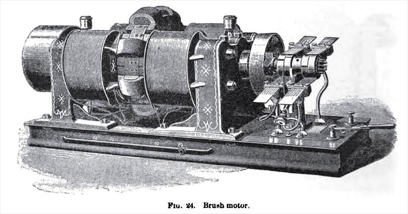
The Brush motor, which is illustrated in the engraving. Fig. 24, closely resembles the Brush dynamo, but the devices added to the machine for the purpose of securing steadiness of power and constancy of speed under all loads merit a detailed description. It will be seen that, mounted on the shaft between the commutator and the journal bearing, there is a cylindrical shell. This shell contains the governor by which the speed of the motor is maintained constant. The mode of regulation adopted by Mr. Brush consists in causing the governor to adjust the commutator automatically with relation to the brushes. To this end the commutator segments are mounted upon a sleeve on the shaft, so that they can be revolved to any desired extent under the influence of the governor.
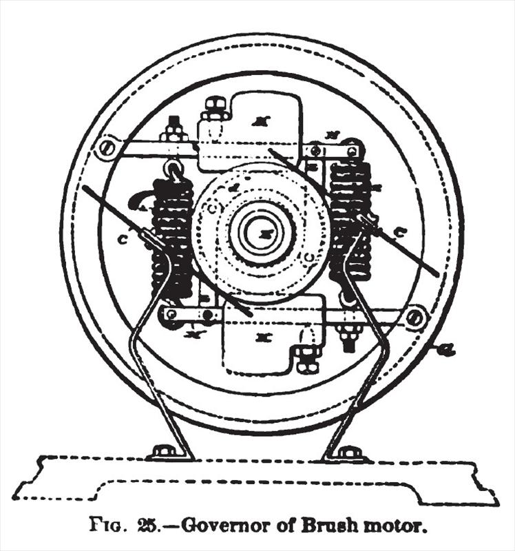
The illustration, Fig. 25, shows the governor in detail. As will be seen, the commutator brushes, C C, remain fixed, and loosely mounted on the shaft, E, is the commutator sleeve, a which turns freely. The commutator sections, d, are insulated from the sleeve, o, and are connected to the armature bobbins by flexible wires, so as not to interfere with the rotary adjustment of the commutator. To the inner periphery of the cylindrical shell, G. which is bolted to the shaft, the governor arms, HH, are pivoted. The inner free ends of the arms are connected to the opposite arms by means of spiral springs, II. In addition, the arms carry each an adjustable weight, K. The links, L L, attached to the arms, HH. are connected to a disk upon the commutator sleeve. Hence, it will be readily understood that as the governor shell rotates with the pivoted weights, K K, the latter, by centrifugal force, will be removed toward the periphery of the shell, and, through the medium of the connecting links, L L, will impart a rotary movement to the commutator, varying its position on the armature shaft.
The action of the governor is precisely analogous to that in a steam engine. When in a state of rest, the springs draw the weights toward each other and maintain the commutator segments at the maximum point of effect with relation to the brushes. When current is switched on to the motor, the governor weights in their revolution are thrown outward and rotate the commutator, carrying the maximum points away from the contact points of the brushes and in the direction of rotation of the armature. This action decreases the effect of the driving current until a point is reached where the effect of the driving current is balanced by the load on the motor, and the speed of the latter remains constant. Now, should the speed of the motor be retarded by a decrease of current strength with no corresponding diminution of load, or by an increase of load with no increase of current strength, the governor balls will be retracted and drawn toward each other by the spiral springs, and thereby rotate the commutator in a direction opposite to the motion of the armature shaft, the effect of which is to move the maximum points on the commutator nearer to the brushes, and thereby increase the speed of the motor. On the other hand, should the speed of the motor
be increased above the normal rate, owing to an increase of current strength or to a decrease of load, the governor balls will be caused to recede from each other and rotate the commutator in the same direction as that of the armature shaft, and cause the maximum points on the commutator sections to be moved away from the brushes, and thereby decrease the speed of the motor. In this manner provision is made for all contingencies affecting the working of an electric motor. |
|
 1895 Brush Electric Co., Brush Electric Motor
 1895 Brush Electric Co., Brush Electric Motor Governor
|
|