|
Title: |
1895 Article-C. & C. Electric Motor Co., Electric Motors |
|
Source: |
Modern Mechanism 1895 pgs 543-544 |
|
Insert Date: |
9/6/2011 8:05:54 PM |
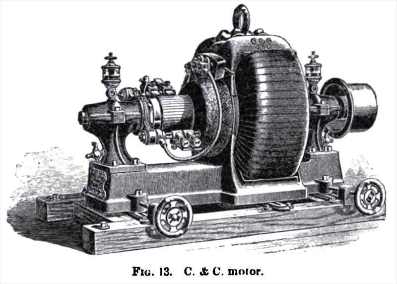
The latest type of C. & C. motor is shown in Fig. 13. The magnetic circuit is of the consequent type, which gives the greatest possible compactness of design. It is made in the circular form, having divided or parallel circuits, meeting at top and bottom, and passing together through the armature core. It consists of two cores, shaped like segments of a circle, bolted to pole pieces at both ends, surrounding the armature. The cores are of wrought-iron, planed off at the ends to an angle of 90% so that when the machine is put together each core and pole piece forms a quadrant of a circle, the center of which coincides with the center of the armature shaft. This construction gives a very short magnetic circuit, free from corners or projections where leakage may occur, and makes the motor exceedingly compact for a given power. The pole pieces are of cast-iron, of much greater cross-section than the cores, the lower one being cast in one piece with the base. The poles enclose about 280" of the armature circumference. The field-magnet coils are wound directly on the cores by hand. The armature core is a drum made up of thin disks of sheet-iron, insulated carefully from each other. These are stamped with a hole in the center for the shaft, and after placing them on the shaft they are pressed together with great force. Iron arbor plates, keyed to the shaft at the ends, hold the disks firmly in position, and are themselves held by nuts screwed on the shaft. These disks are in addition held together by long bolts, whose heads are sunk into the arbor plates, thus ensuring an absolutely rigid and solid core. A modification of the Siemens winding is employed, and the wire is proportioned to carry an excess of current above the full load of the motor, without undue heating. The commutator is built up of cast tempered or of hard-drawn copper bars of tapering cross-section, beveled at each end. The insulation between the bars is of the best mica, made up of thin strips to the proper gauge. They are held together by steel collars, turned on one side to the same angle as the ends of the bars, and threaded to receive nuts, which are screwed up with great force against the collars, thus holding the bars firmly in place without allowing them to twist out of line. The sleeve and collars are carefully insulated from the bars by thick layers of mica.
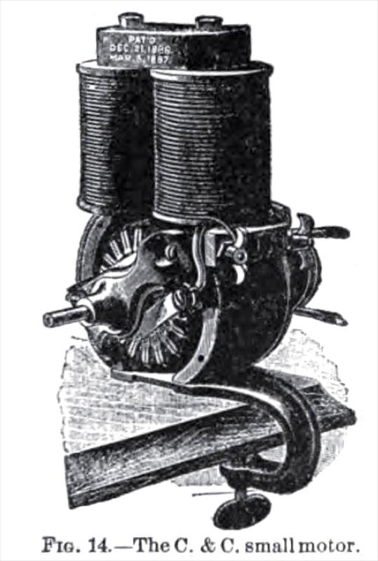
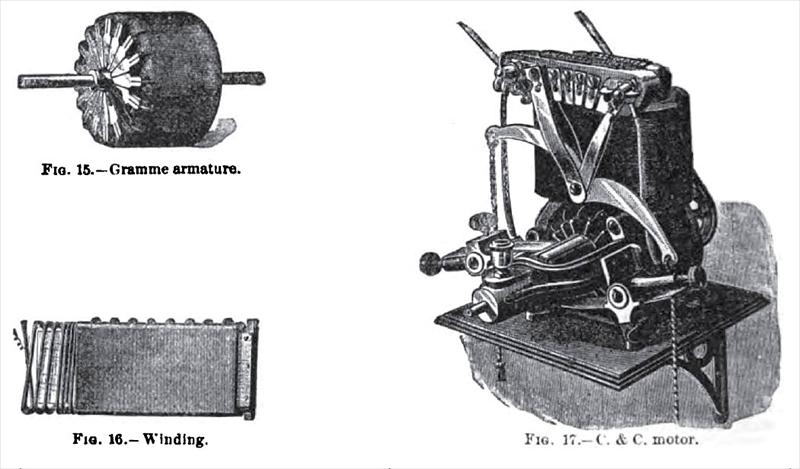
The C. & C. small motor, shown in Fig. 14, is made up of interchangeable parts. The cores and pole pieces are drop forged, and afterward finished to gauge. The Gramme ring armature is shown in Fig. 15. The core is formed of punched sheet-iron semicircles, upon one side of which tissue paper is pasted. These semicircles are laid together, with the ends of alternate rings projecting at either edge of the built-up half cylinders, so that the edges of the two half cylinders so formed will interlock. The half circles and a rivet passed through, uniting them, lock the parts of a hinge. Upon this split ring is slipped a flat helix of wire, forming the entire winding of the armature in one layer, so that the operation of slipping it on is very simple. The wire used is flat, as shown in Fig. 16. The small i horse-power C. & C. motor, shown in Fig. 17, is interesting as being made with a complete Wheeler regulator, by which it can be run at any speed. |
|
 1895 C. & C. Electric Motor Co., Electric Motor
 1895 C. & C. Electric Motor Co., Electric Motor
 1895 C. & C. Electric Motor Co., Electric Motor
|
|