|
Title: |
1907 Article-A. H. Alberger Co., Buffalo Tandem Gas Engine (part 1) |
|
Source: |
Power Magazine Feb 1907 pgs 126-128 |
|
Insert Date: |
9/3/2011 8:58:10 PM |
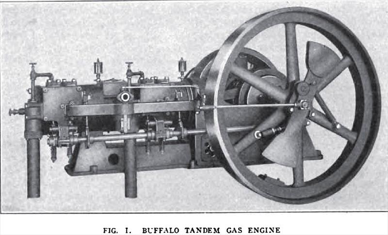
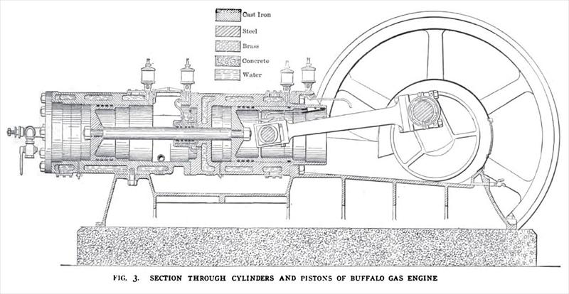
The A. H. Alberger Company, Buffalo, NY, is building a line of single acting tandem gas engines, which employ a number of original features. Fig. 1, herewith, shows the general appearance of the single engine on the valve-gear side and Fig. 2 shows a twin engine from the other side. The prime feature of differentiation from common practice is the use of single-acting cylinders in tandem. The piston-rod from the rear cylinder passes through a stuffing-box in the head of the front cylinder, and the piston in this cylinder is of the trunk type, with the connecting-rod wrist-pin set across it. Fig. 3 is a longitudinal section of the engine and illustrates the constructional features of the cylinders, pistons, and other large parts. It will be noticed that the rear piston is made short and light; this is practicable because there is no side thrust on this piston. Access to the rear cylinder is obtained by removing the head, which, it will be noted, is not water-jacketed; removing the connecting-rod, unbolting the piston-rod and drawing out the trunk piston gives access to the front cylinder. The removal of the connecting-rod is easier than an inspection of Fig. 3 would indicate. The wrist-pin is held in the piston by two caps which may be readily unbolted by means of a socket wrench; then the connecting-rod with the wrist-pin in its box is withdrawn. Fig. 4 illustrates this construction, which is a front view of the front piston. Fig. 5 is a view of the two pistons and the piston-rod, and shows the arrangement of packing rings and the shoe which catches oil from the front oil cup shown in Fig. 3 and delivers it to a small pipe inside the piston which carries it to the wrist-pin oil funnel.
The piston-rod runs in a water-jacketed stuffing-box which is packed with cast-iron spring rings. These rings are similar to the ordinary cast-iron snap rings used in pistons, except that the "spring'' is not outward, but inward, so that the rings clamp the piston-rod. The casing surrounding and carrying the rings is in two water-jacketed halves, bolted together, the joint being ground. The flange of the complete stuffing-box is then bolted to the front cylinder-head. Oil is fed between the rings, as indicated in Fig.3 years without receiving a moment's attention, and, without exception, working as perfectly as when the engines were new. The crank-shaft and connecting-rod are made of open-hearth steel, each forged in one piece and cut from the solid. The crank is fitted with balance weights, which are secured to the crank-discs. The connecting-rod is fitted at the crank end with a bronze box of the marine type lined with Babbitt metal, and with a bronze box with wedge adjustment at the piston end. The frame is a single heavy casting of the double-wall type, strongly braced and designed for great strength and rigidity. It is sloped well forward from the main bearings, and is spread laterally for distributing the weight on the foundation. The metal is carried in straight lines between the front cylinder yoke and the main bearings. The main bearings are split at an angle, so that the rigid frame receives the pressure of the shaft when the engine is in operation. The bearings are lined with Babbitt metal. An oil groove is cast around the bottom of the frame to protect the foundation. A door is provided on one side of the frame for convenience in grouting when erecting the engine on foundation. The interior of the frame is used as a settling chamber for any grit or foreign material, which may be present in the air used by the engine. The door on the side of the frame has holes through which air is admitted, and the air passes to the intake pipe from a point near the rear end of the frame extension, which supports the cylinders. The cylinders are cast separately and bolted together and to the frame, this method of construction being considered as insuring positive alignment. The usual secondary side shaft imparts motion to the valves and igniters. It is driven from the main shaft through two to-one spiral gears, the engine operating on the Otto or four-stroke cycle. It may be incidentally mentioned that these are the only gears used on the engine. The two valve chests and their auxiliary parts are similar in all respects. An extension from the lower side of each valve chest forms a hanger, which carries a journal box for the side shaft, as shown in Fig. r. A hand-hole over each valve affords access thereto, and also permits the valve to be withdrawn from the chest. The valves are vertical and of the poppet type with guides. Each valve is mechanically actuated by a simple cam and lever movement. The lever is forked at the valve-stem end and pushes, when the valve is being lifted, against a collar on the valve-stem. Side thrust is obviated by the interposition of a metal roller between each fork of the lever and the lift collar on the valve-stem, as shown in Figs. 6 & 9. It will be noticed that this roller is flattened on top, affording a sliding contact with the lift collar, so that it rotates only as much as may be required in its cylindrical bearings in the fork of the lever. This arrangement is said to prevent side thrust entirely. The tension of the valve spring is adjusted by means of the nuts shown on the lower end of the valve stern. The valves are made with square bosses on the heads to permit regrinding in position. The two valve-stem guides are cast-iron bushings, which are easily and cheaply renewable. Each valve is lifted from its seat by the lever and closed by its own weight, assisted by the spring. |
|
 1907 A. H. Alberger Co., Buffalo Tandem Gas Engine
 1907 A. H. Alberger Co., Buffalo Tandem Gas Engine
 1907 A. H. Alberger Co., Buffalo Tandem Gas Engine
|
|