|
Title: |
1887 Article-Diehl & Co., Electric Motor |
|
Source: |
The Electric Motor and its Applications 1887 pg 133 |
|
Insert Date: |
9/1/2011 7:42:32 PM |
|
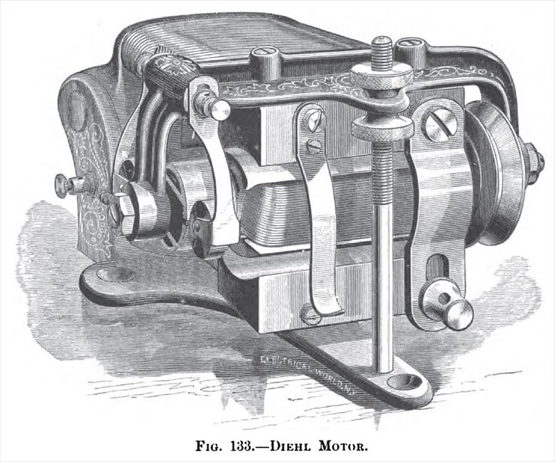
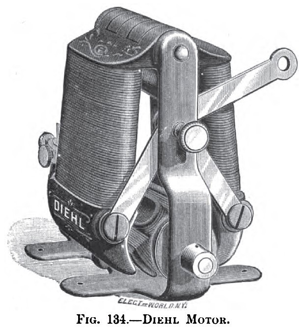
At the Singer Manufacturing Company's exhibit in the International Electrical Exhibition at Philadelphia in 1884 were seen several sewing machines run by various electric motors invented by Mr. Philip Diehl, the inventor engaged by the sewing machine company, and one whose other work in the practical application of electricity has been marked by great originality. One form of motor is made part of the flywheel of the sewing machine, and the one we illustrate by Fig. 133 shows the motor at about two-thirds size. If the pole be swung downward until its lowest limit is reached, the electric circuit is broken entirely at the point where the button on the under pole and the spring projecting from the upper pole meet. The post with the two jam nuts on it is for the purpose of fixing the position of the upper pole. The armature core axis and pulley are cast as one piece of iron, and the armature is of the Siemens H type. One pole of the armature core is extended and bent so that the axis at the commutator end is in its proper place, and there is a space between this extension and the other pole. At the other end of the other pole a like extension for the pulley axis is provided. Thus there are longitudinal and transverse spaces lengthwise around the core to receive the coil; and yet the poles are not connected by iron except within the coil. The commutator is of the kind usually attached to bi-polar armatures—that is to say, it has two sections. One of the most novel an ingenious motors is that shown in Fig. 134. This motor is also the invention of Mr. Diehl. The present motor, though built on the same principle as the one exhibited by the inventor at Philadelphia, in 1884, and illustrated above, differs considerably from it in construction and general appearance. By referring to the engraving, it will be seen that the field magnets are placed vertically and hinged at the top, being supported by two side rods, cast solid with the base. The lower ends of the field magnets encircle the armature, which is also carried by journal bearings in the side rods. The method of regulation of the motor consists in separating the pole pieces from the armature. This is accomplished by means of two connecting rods fixed to the lower ends of the magnets and joined together by a pin which slides in a slot on the upright. A rod connected to the pin serves to raise and lower the upper ends of the two connecting rods, and in doing so, the field magnets are separated or brought together as the case may be. When used in connection with a sewing machine, the motor is secured to the under side of the table in an inverted position, and the regulating lever connected to the treadle. In this position the field magnets fall apart of their own weight and the machine does not work. It is only when the treadle is pressed and the magnets are brought together that motion is obtained. It is evident that by varying the distance between the armature and the magnets any desired speed can be obtained for fast or slow work. The motor is finished in a very ornamental style, and runs very smoothly. The armature shaft is provided with a pulley, and its end is bored so that the power can be transmitted by belt or applied directly, as when driving a fan. |
|
 1887 Article-Diehl & Co., Electric Motor
 1887 Article-Diehl & Co., Electric Motor
|
|