|
Title: |
1895 Article-Diehl & Co., Electric Motor |
|
Source: |
Modern Mechanism 1895 pgs 540-542 |
|
Insert Date: |
9/1/2011 1:22:18 PM |
|
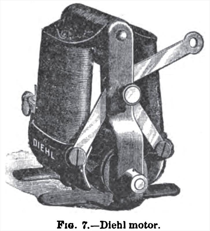
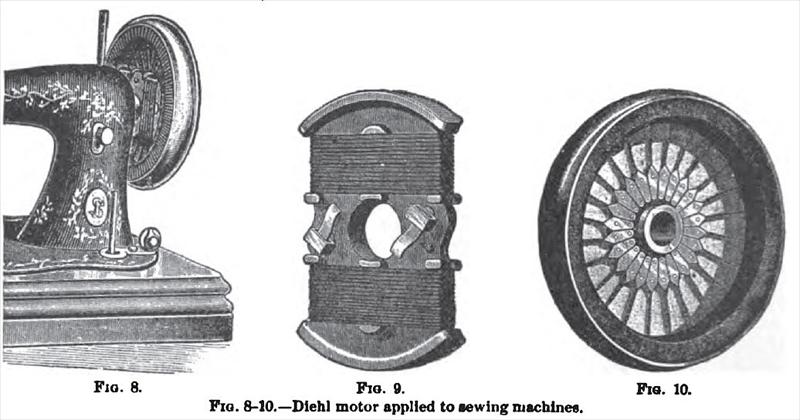
At the Singer Manufacturing Co.'s exhibit in the International Electrical Exhibition at Philadelphia in 1884 were seen several sewing machines run by various electric motors by invented Mr. Philip Diehl, the inventor engaged by the sewing machine company. A later design is shown in Fig. 7., in which it will be seen that the field magnets are placed vertically and hinged at the top, being supported by two side rods, cast solid with the base. The lower ends of the field magnets encircle the armature, which is also carried by journal bearings in the side rods. The method of regulation of the motor consists in separating the pole pieces from the armature. This is accomplished by means of two connecting roils fixed to the lower ends of the magnets, and joined together by a pin which slides in a slot on the upright. A rod connected to the pin serves to raise and lower the upper ends of the two connecting rods, and in doing so the field magnets are separated or brought together, as the case may be. When used in connection with a sewing machine, the motor is secured to the under side of the table in an inverted position, and the regulating lever connected to the treadle. In this position the field magnets fall apart of their own weight and the machine does not work. It is only when the treadle is pressed and the magnets are brought together that motion is obtained. It is evident that by varying the distance between the armature and the magnets any desired speed can be obtained for fast or slow work. The armature shaft is provided with a pulley, and its end is bored so that the power can be transmitted by belt or applied directly, as when driving a fan. To avoid the necessity of belting, and at the same time do away with tho presence of an auxiliary machine on the board for driving, Mr. Diehl conceived the idea of combining the motor and sewing machine into a practical unit, as shown in Fig. 8. The motor is completely housed within the fly-wheel of the machine, and connected directly with the driving shaft, so that all gearing is obviated. Tho details of the arrangement will be readily understood from Figs. 9 and 10, which show respectively the field magnet and armature of the motor. The magnet, which consists of a single piece, is wound with wire connected to the two terminal brushes shown. This magnet is permanently fixed to the hub through which the shaft passes. The armature, shown in perspective in Fig. 10, is of the Gramme type, and is held in position within the rim of the wtieel. The wires leading from the periphery connect to the commutator at the hub, and the brushes on the magnets bear against the segments. The wires leading to the motor pass up through the hollow casting of the frame, and are connected to a switch, by which the machine can be started and stopped at will. The flywheel is provided with a clutch or stop motion in connection with the shaft, so that it may be connected with the latter, or turned loose, as is common in sewing machines —the wheel being disconnected from the shaft when winding bobbins. This is accomplished by a turn of a thumb-nut at the rear end of the machine. By unscrewing this nut entirely, the armature may be slid out completely, so that it may be examined, should necessity require. This also exposes the field magnets and brushes, so that they can be easily gotten at for examination and attention. |
|
 1895 Diehl & Co., Electric Motor
 1895 Diehl & Co., Electric Motor Parts
|
|