Image
|
Title: |
1904 Article-A. W. Stevens & Son, Steam Traction Engine |
|
Source: |
English and American Steam Carriages and Traction Engines 1904 pgs 414-416 |
|
Insert Date: |
8/29/2011 9:08:11 PM |
|
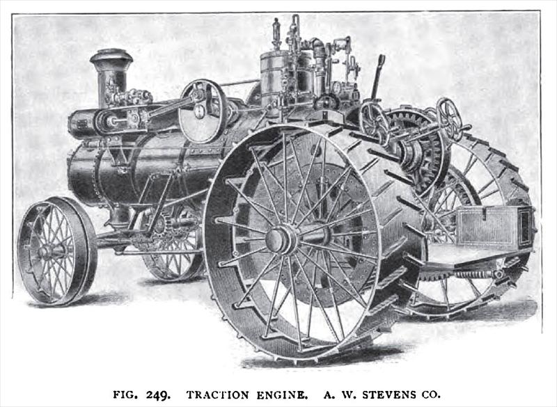
A. W. STEVENS & SON CO. — It is said “the demand for practical machinery is increasing, and that the fad for something experimental and out of the ordinary way is fast wearing itself out.” Fig. 249 shows a 25 horse-power simple traction engine; the diameter of the cylinder is 9¼ in., and the stroke 12 in., the indicated horse-power is 50. An English traction engine of this size has developed just under 70 horse-power on the brake, running at 160 revolutions per minute, the steam pressure being 140 lbs. per square inch. If the engine above had run at 200 revolutions, instead of 160, a much higher power would have been developed by the English type. The makers describe this engine “as beautiful in construction, a giant in strength, designed for heavy work of all kinds on road or belt.” A Corliss pattern frame is used, an over-neck crank-pin, and a balanced disc. The hind axle is placed across the boiler front beneath the fire-hole and a foot-brake is provided; The brake-drum is keyed to the counter-shaft. A brake is not often provided on the American traction engine. The steam is taken from the top of the dome, the pipe passing through the hottest part of the boiler, thereby super-heating the working steam before it enters the cylinder. A Pickering governor is employed; it is placed horizontally so as to reduce vibration on the road. In England, the governors are never used when the engine is traveling on the road; it is only used when the engine is driving machinery from the flywheel. Coil springs are placed in the steering chains. A cast-steel connecting-rod is used; it is three times the length of the stroke. The compensating gear is placed on the countershaft, the power is transmitted from the countershaft to the rims place near the periphery of the driving wheels. A single eccentric reversing-gear is used; a fiction clutch is employed, for which the makers claim many advantages. The style of driving-wheels and the shape of the cross-strips can be seen from the illustraation. |
|
 1904 A. W. Stevens & Son, Steam Traction Engine
|
|
|
|