|
Title: |
1904 Article-Wallis & Steevens, Steam Motors |
|
Source: |
English and American Steam Carriages and Traction Engines 1904 pgs 358-361 |
|
Insert Date: |
9/1/2011 8:06:03 PM |
|
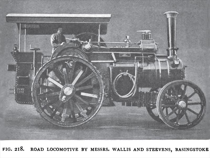
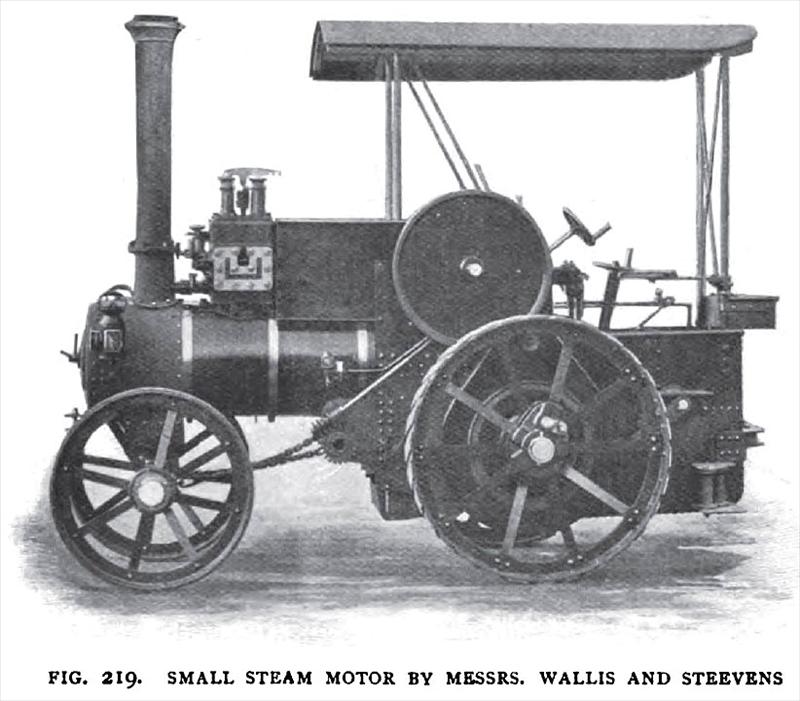
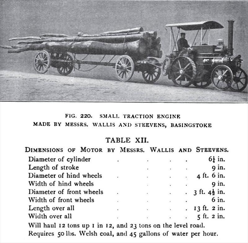
MESSRS. WALLIS AND STEEVENS — The eight horse-power nominal single-cylinder road locomotive shown by Fig. 218 is of the three-shaft type. In the opening sentences of this chapter, mention was made of three-shaft and four-shaft traction engines; the makers claim some advantages for their system of construction—a saving of wearing parts, a stronger, simpler, and handier engine. The fast-speed pinion is the one furthest away from the crank-shaft bearing, and the small pinion slides inside the fast-speed pinion in the usual manner. A steam-jacketed cylinder is placed at the smoke-box end of the boiler; the jacket is in direct communication with the steam space of the boiler. The flywheel is fitted with a wrought-iron plate to form a disc, instead of the wheel being cast on a disc as is the general practice. The engine is mounted on springs, as illustrated in Chapter VII. This arrangement, it is stated, is simple and efficient; the spring motion is taken on the main axle, which is only allowed to be actuated about three eighths of an inch. The springs in no way affect the power of the engine, "as, in the makers' opinion, results if the wheels are made to spring, as with some arrangements produced by other firms." By the turning of a screw the power of the spring can be adjusted, and if desired, the springs can be put out of action altogether. The fore tank is shown with the water-lifter on the top. A Ramsbottom safety-valve is mounted on the cylinder-top, the governors, winding-drum brake; an awning over the driver and a coal rack are included in the outfit. The driving-wheels are constructed of tee-rings, joint strips, and steel treads, all riveted up by machinery under a pressure of 50 tons. The next illustration, Fig. 219, shows the flywheel side of a three horse-power traction engine, made sufficiently light so as to run under the Light Locomotive Act of 1896. The next, Fig. 220, represents a light locomotive or steam motor drawing a loaded wagon. Where there is much work to be done, the saving effected by using steam in lieu of horses is great. These motors are not designed for the purpose of conveying passengers, or for high-speed light parcel delivery, but are made to do the work of one, two, or more heavy draft horses. For this work the makers think it is far preferable for the motor to be independent of the vehicle to be drawn. The engine is easy to handle, divides the weight over eight instead of four wheels, i.e. the motor and the load in a wagon. Two travelling speeds are provided, enabling the motor to run from two to five miles an hour. The motor can be attached to any van, wagon, or trolley now in use with horses. It is constructed for hauling loads of from four to six tons, and works at a small expenditure of fuel and water. The working parts of the motor are all cased in, so as to be less liable to frighten horses ; the brake acts on the rim of the driving-wheel, as shown. There is undoubtedly a great future for the small and light traction engine; the restrictions of the law have retarded progress, but now that motors can be built to comply with the Act of 1896, these restrictions are removed, and the little engines are as free on the road as any other vehicle. |
|
 1904 Wallis & Steevens, Steam Road Locomotive
 1904 Wallis & Steevens, Small Steam Motor
 1904 Wallis & Steevens, Small Steam Motor & Wagon
|
|