|
Title: |
1904 Article-Clayton, Shuttleworth & Co., Steam Traction Engine (part 1) |
|
Source: |
English and American Steam Carriages and Traction Engines 1904 pg 307 |
|
Insert Date: |
8/16/2011 1:06:07 PM |
MESSRS. CLAYTON AND SHUTTLEWORTH— The first illustration, Fig 194, represents a general purpose traction engine, in the design of which are embodied all the up-to-date improvements of the day. The boiler is made entirely of steel and stayed for a working pressure of 140 lbs. to the square inch. The top of the fire-box is stayed directly to the arch-plate of the outer shell; it can be more easily kept clean than was the case with the roofing bars formerly used, which afford lodgment for scale and sediment. These roofing stays are placed vertically, and pitched 4 in. apart; they are screwed in the fire-box top and the arch-plate, the outside end is riveted over, the fire-box end is secured with a nut and a suitable joint between the nut and the plate. Boilers of this type have been used for many years with very good results. Figs. 195 & 196 represent a side view and an end view of a large compound road locomotive mounted on springs, intended for colonial purposes. The engine has been designed for hauling heavy loads for long distances without frequent stoppages for taking in water or fuel. The high and low pressure cylinders are placed side by side, the slide-valves are arranged above the cylinders, and actuated by radial valve-gear, such as, or similar to Joy’s, which produces an excellent distribution of steam to both cylinders. By removal of the top cover of the cylinder, access can be gained to the high and low-pressure slide-valves, the throttle valve and the stop-valve, foe adjustment, etc. In this arrangement of engine, excentrics are dispensed with for working the slide-valves; the two speed first-motion gearing can be place inside the box brackets in a four-shaft compound engine without crowding. The same gearing can be used throughout as for a single cylinder traction engine. The slide-valve faces and valve rods being parallel with the centre line on the cylinders, the slide-faces are more easily tooled and the valves are readily accessible for setting, examination and repairs. By this patent system an economy of space on the crank-shaft is effected, which permits the introduction of three-speed gearing when desired. High-pressure steam can be admitted to the low-pressure steam chest for starting, so the engine for this time being will work the same as an ordinary double-cylinder engine. These engines are made under Shuttleworth and Fletcher's patent. The radial valve-gear is shown by Fig. 197. A section of the compound cylinder by Fig. 198, designed by the writer and patented in 1899. No. 16,668.
The engine is supplied with a supplementary tank beneath the boiler barrel, this tank is connected to the hind tank by means of a large pipe with a cock, which can be shut off to prevent the loss of water when travelling up steep hills. A Worthington or other steam pump is mounted on the tank, and draws water from the tank for feeding the boiler. An injector is also employed which draws its supply from the hind tank. On this fore tank is also mounted a water-lifter with 25 feet of hose pipe for drawing water from a river or wayside stream into the tanks; the work of filling both the tanks only takes a few minutes. A powerful block-brake acts on the periphery of both the hind driving-wheels. A slip winding-drum supplied with 75 yards of steel wire rope is mounted on the hind axle; the rope can be paid out as the engine travels forward, effecting a great saving of time and labor. The winding-drum offers the readiest means of pulling loads out of places inaccessible to the engine, or for hauling wagons up very steep inclines. As the engine travels up the steep bank the rope is drawn out during the ascent; when the engine reaches the top, the brakes are applied and the wheels are scotched; the engine proceeds to haul one or more wagons up the hill, or across a river, and then passes on the journey in the usual manner. The driving-wheels are 7 ft. diameter, and 2 ft. across the face; they are built up of three steel tee-rings with inside tire-plates and the usual diagonal cross strips. The leading-wheels are 4 ft. 6 in. diameter, and 9 inches on the face. An auxiliary valve-gear is applied to these compound engines for admitting a breath of high-pressure steam into the low-pressure valve-chest for starting, or for getting out of difficult places; the valve is closed by a spring as soon as it is released. A foot-board extends along the boiler barrel for giving access to the engine for lubricating, cleaning, or adjusting the working parts; a ladder is also provided, as shown. A disc flywheel and side-plates are fitted so as to reduce the risk of frightening horses. The engine is provided with a light awning over the foot-plate and the hind part of the engine. Two mud-holes are provided in the corners of the saddle-plate which facilitate the raking out, as shown by the sketch, Fig- l99. There are three other mud-holes, also arranged in suitable places. The steering-gear chain barrel is placed beneath the fore tank, and the chains lead off quite straight to the quadrant on the fore axle. The working pressure is 180 lbs. to the square inch, the hydraulic test pressure 300 lbs. The travelling speeds are three and five miles an hour. Many road locomotives are provided with three speeds—two, four, and six miles an hour. A second arrangement of spring mounting can be applied, in which the movement of the axle and the first countershaft in no way affect the mesh of the gearing.
Fig. 200 shows another compound road locomotive, provided with an awning from end to end. This engine is mounted on springs at the fire-box and also at the smoke-box end.
A considerable number of these road locomotives have been shipped to Australia, South Africa, New Zealand, Egypt, France, Spain, Portugal, etc. Several of them are used for ploughing by direct traction in Africa and Europe, special provision being made for attaching the ploughs to the tender of the engine. Quite recently, compound road locomotives have been shipped with ash-pans suitably made for the engines to cross rivers, three or four feet deep, without the water putting out the fires. Another 8 horse-power road locomotive in Russia, fitted with oil-burning apparatus, hauls loads of 27 tons up a mountain-side, over the worst possible roads, to a height of 300 feet, part of the incline being 1 in 9. An ordinary 8 horse-power traction engine is constantly hauling 33½ tons gross in three trucks, at four miles an hour on the level, and up a rise of 1 in 15. The same engine travels sixteen miles on one filling of the tanks. |
|
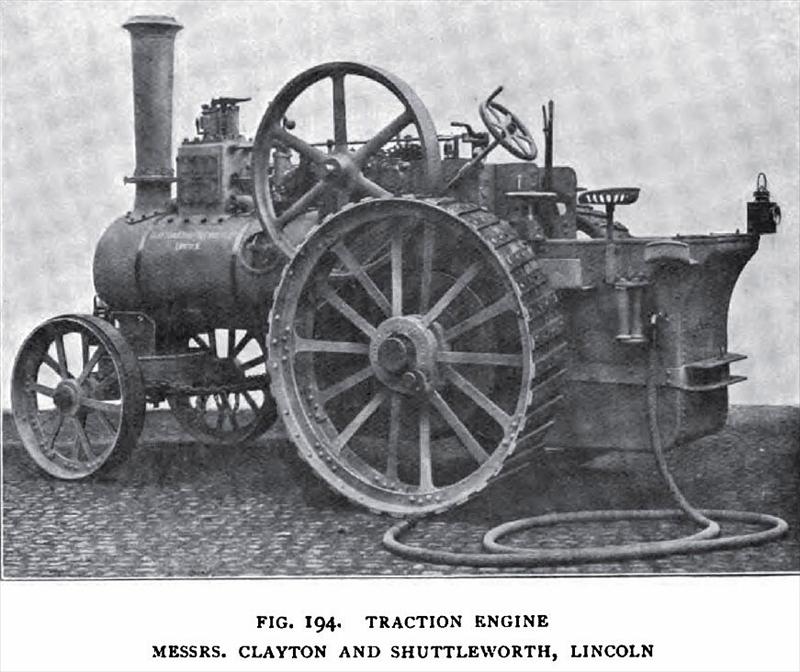 1904 Clayton, Shuttleworth & Co., Steam Traction Engine
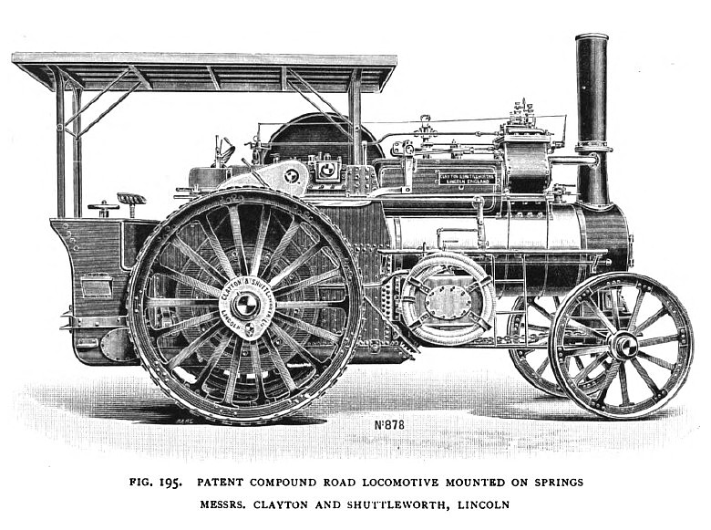 1904 Clayton, Shuttleworth & Co., Compound Steam Road Locomotive on Springs
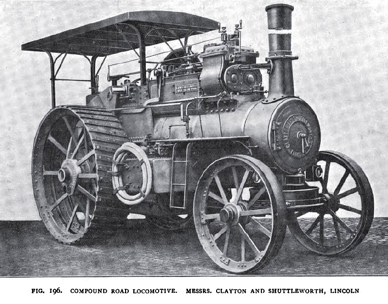 1904 Clayton, Shuttleworth & Co., Compound Steam Road Locomotive
|
|