|
Title: |
1870 Article-Reed & Bowen, Tire Upsetter, Punch & Shear |
|
Source: |
English Mechanic and the Mirror of Science 29 Apr 1870 pg 123 |
|
Insert Date: |
1/2/2023 3:00:13 PM |
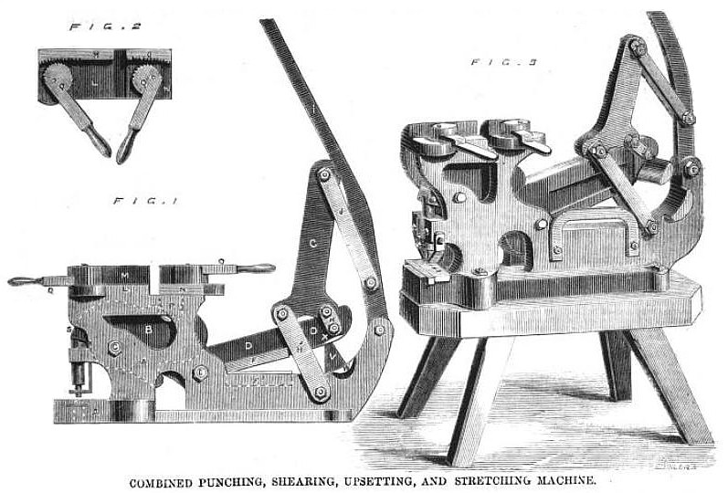
Sir,—I send you drawings of a very ingenious and useful little machine of American origin, which has been lately introduced into this country by Messrs. Towle and Harding, of 98, Newgate street. This machine, which is constructed by Messrs. Reed and Bowen, of Boston, U.S., is intended for shearing, punching, bending, and shrinking or stretching tires or hoops, and when constructed in the form we illustrate is adapted for being worked by hand power. The machine, in fact, although capable, when worked by one man, of cutting easily bar iron 2½ in. by ½ in. or 4 in. by 3/8 in., weighs only 350 lb.
Referring to Fig. l, it will be seen that the main frame A of the machine, consisting of the two sides and the top and bottom is cast in one piece, the cam B being placed between the two sides and hung on the pin C. The first lever D works into this cam, and is hung on the pin E, the knife F. for shearing, being attached to this lever and the knife F2 to the main frame A, The second lever G is connected to the first lever D by the straps H, and to the main frame A by the strap H. The third or hand lever I is connected to the lever G by the straps J, and also to the main frame A by the bolt K. This forms a very powerful arrangement of levers, giving with 100 lbs. on the hand lever a pressure of over 52,0001b. on the shears and 72,000lb. on the punch. The straps H H3, and J are in pairs, one on each side of the machine.
The operation of shearing is performed by placing the metal to be cut between the knives F and F2, and then bearing down on the hand lever I. The tire shrinker and stretcher consist of a block L, which is part of the main frame A. On the back of this block there is a projection M, against which the tire rests, and which is provided with teeth at the end so as to keep the tire from slipping; there is also a movable block N, which has a similar projection O, and which is also provided with teeth in the same manner as the other. The movable block N has a tooth P on the under side working down into the cam B, and is moved in the operation of shrinking a tire by the hand lever I. Upon each of the blocks L and N Is a toothed eccentric Q, for the purpose of holding the tire while the block S is being carried towards the block L. The operation of stretching a tire is performed by reversing the eccentrics Q, and carrying the lever the other way.
The punch socket R is connected to the cam B by the pin S, and passes through the guide T, the die being confined in the main frame A. The operation of “gumming," or cutting between the teeth of saws, is performed by a punch and die made especially for that purpose. A guide V is cast on the main frame A, so as to keep the lever D from being forced off in the operation of cutting. Finally, a concave projection W, which is cast on the main frame A, projects about 3 in., and a corresponding convex projection X is casted in the lever D. These parts are used for bending iron into any required form, and they form, according to Engineering, a useful addition to a very useful machine. |
|
 1870 Article-Reed & Bowen, Tire Upsetter, Punch & Shear
|
|