|
Title: |
1895 Article-Jones, Lamson & Co., Flat Turret Lathe |
|
Source: |
Modern Mechanism 1895 pg 464-467 |
|
Insert Date: |
6/20/2011 9:56:09 PM |
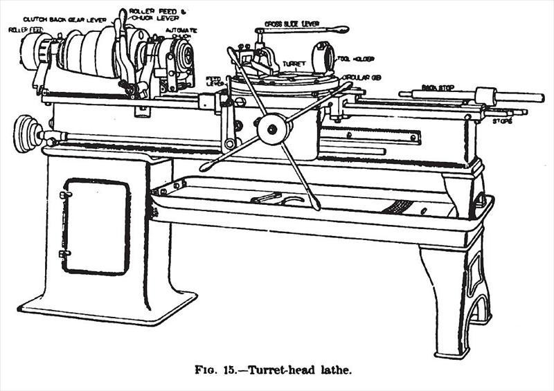
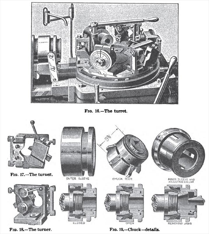
Jones & Lamson's Turret - Head Lathe.—Figs. 15 to 22 illustrate a turret-head machine, which embodies several departures from the regular practice in such machinery, enabling certain classes of work to be done on it that have not heretofore been attempted on turret-head machines. It is built by the Jones & Lamson Machine Co., of Springfield, Vt. The usual form of turret and mounting for the same has been entirely abandoned, and what maybe termed a turn-table is mounted upon what resembles the ordinary lathe-carriage.
This carriage is fed by rack and pinion with pilot-wheel in the ordinary manner, or automatically, as may be desired, and the turret revolves automatically. The carriage slides on large 90° Vs, and is gibbed to the bed outside front and back. The various tool-holders, turning devices, cut-off slides, etc., by which the work is done, are simply attached to the top or upper surface of the turret by square tongues and grooves with bolts. The turret, which is proportionately much larger in diameter than usual, is gibbed all round its outer circumference, and the locking-pin engages there. The cutting tools do not extend out over the turret, but are usually about vertically over the point of engagement of the locking-pin, a fact which practically relieves the central bearing of the turret of all stress during the cut, and enables the tool to be held more steadily, other conditions being the same. There are six slots for as many tool-holders, and there is a separate stop for each one, which Is adjustable independently of all the others, so that the point at which the feed will be automatically released, and the motion of the slide positively arrested, may be independently fixed for each tool and operation, instead of its being necessary to set all the tools but one to suit the point of feed-release. The revolving mechanism is also arranged so that it can be made to act at the moment any tool clears the work, so that no loss of time results from running back farther than is necessary for any given tool. Where less than the full number of tools are used, the revolving mechanism can be made to skip one or more places, so as to bring the next tool into position wherever it may be. Fig. 15 is a perspective view of the machine, and Fig. 16 is an enlarged view of the turret, with six tools set upon it. While the ordinary turret-head lathe or screw-machine will distance the lathe for work to which it is adapted, it has its limitations, one of these being that there must be a comparatively large number of pieces to make that are just alike, otherwise it will not pay to set the various tools and arrange the machines for doing the work; the number of pieces needed to make it pay to do this depending mainly upon their character. This difficulty the builders of this machine have attempted to overcome by arranging the tools so that they can be set with a facility approaching that of lathe-tools ; and it is claimed by them that, if there is but one piece to do, it will usually pay to do it on this machine, and that it is therefore well adapted to general machine shop-work within its range of capacity, which is for work up to 2 in. in diameter and 24 in. long.
Turret-head machines have not heretofore been constructed for work of this length, nor for doing work so long in proportion to its diameter as can be done on this machine.
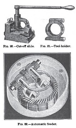
Long work of small diameter is finished by means of the tool shown in Figs. 17 and 18, the former being a front view and the latter a rear view of the tool, which is called the "turner." The tool is adjustable by screws, and can be moved to or from the work by a cam, which is moved by a small lever, so that the tool may be run into the work for necking, or. in the case of long and slender work, the tool is opened, run up close to the chuck, where the work is held securely, and the tool run in to the required depth. It is then fed backward toward the end of the work, the usual back-rest following behind the tool, and bearing on that portion of the work that has been trued. In this way much of such work is finished at a single cut from the rough, though where it is necessary another cut can be run over it in the other direction, the rest in this case, as in the other, following the tool. The cut-off slide, a separate view of which is shown at Fig. 20, is bolted to the top of the turret, as shown by the rear view of the machine, and is so arranged that the turret can be run up under the chuck, and the cut-off used without interfering with any of the other tools. Provision is made for using throe tools in the slide, and as they have the longitudinal motion due to the movement of the turret, and can be fed into the work by a lever and small pinion, the three tools can be used for different purposes, such as necking in, cutting off, or turning if desired. The tool-holder for hollow mills, taps, dies, reamers, drills, etc. is shown by Fig. 21. It is attached to the turret in the same way as the other tools. |
|
 1895 Jones, Lamson & Co., Flat Turret Lathe
 1895 Jones, Lamson & Co., Flat Turret Lathe-Turret & Chucks
 1895 Jones, Lamson & Co., Flat Turret Lathe, Tool Holders & Automatic Feeder
|
|