|
Title: |
1895 Article-William Sellers & Co., Tool Grinding Machine |
|
Source: |
Modern Mechanism 1895 pg 406-407 |
|
Insert Date: |
6/14/2011 7:46:44 PM |
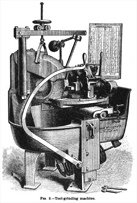
The Sellers Tool Grinding and Shaping Machine, represented in Fig. 2, is intended for grinding and shaping all the faces of almost any kind of lathe, planer, slotter, and shaper tools. The main features of the machine are as follows: A grinding-wheel is mounted in a cast-iron frame forming a large tank, which receives the water used for flooding the tool in grinding. Slide-rests are provided, by which a vertical and two horizontal motions at right angles to each other can be imparted to the tool-holding chuck. The slide-rests and chuck are carried upon a vertical slide, which may be moved up and down by the long lever which is operated by the left hand of the attendant, the object of this movement being to move the tool in a vertical plane up and down past the grinding-surface of the stone, and thus produce a plane surface on the tool. In grinding curved surfaces no vertical movement is given to the chuck holding the tool, but it is made to rotate, to produce the curve desired. If the curve of the tool is not a circular one, then a "former" plate is required. Means are provided by which any sample tool, whether ground by hand or otherwise, can be used as a templet for grinding the "former plate" to be afterward used for the reproduction of the shape of this sample tool. These formers simply consist of small cast-iron plates ¼ in. thick. The chuck which holds the tool can be rotated' in two planes at right angles with each other, and the exact amount of rotation in either plane is indicated by graduated circles and verniers, so that any desired angle of tool or of clearance can be accurately obtained. For grinding the curved-face tools, the former plate is first selected and placed in the machine; then the tool to be ground is placed in the swinging-chuck with the base of the tool toward the left, and pushed forward against the end gauge until the index-finger of this gauge points to the number given in a table furnished by the makers, showing the vertical and horizontal angles which they have found best in practice, plus the amount required to be ground off the tool. The tool is clamped in the chuck and the chuck-swing, so that the entire curve of the tool will rub against the end gauge. The oscillation of the index-figure is noted, and the chuck adjusted by means of the handle on the left, until these oscillations are reduced to a minimum. The tool will then be in the best position for grinding.
For grinding lathe, boring, and chasing tools, planer-hook tools, and slotting-splining tools, supplementary chucks are used and set to the angles given for corresponding straight tools. The periphery of the grinding-wheel is not at right angles to the flat surfaces of the wheel, but is formed so that in the section the grinding surfaces will form a V containing an angle of 90°. With this shape of stone a vertical surface perpendicular to the axis of the stone can be ground by moving horizontally the chuck with tool toward the center of the wheel; then, without disturbing the tool or making any change whatever, a vertical surface at right angles to the former surface can be ground by moving the tool horizontally in a direction parallel to the axis of the wheel. |
|
 1895 William Sellers & Co., Tool Grinding Machine
|
|