|
Title: |
1895 Article-Warner & Swasey Co., Swasey's Gear Cutter |
|
Source: |
Modern Mechanism 1895 pg 395-397 |
|
Insert Date: |
6/14/2011 1:29:11 PM |
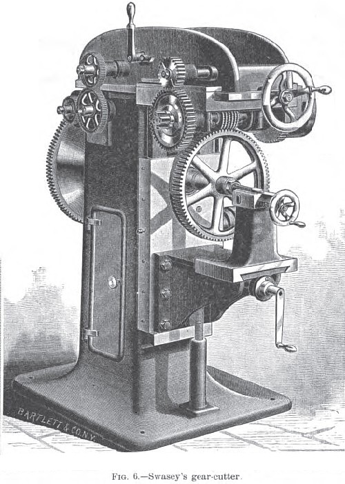
Swasey's Process for Generating and Cutting Spur-Gears.—A new process for generating and cutting the teeth of spur-wheels is thus described by Ambrose Swasey, of the firm of Warner & Swasey, Cleveland, 0. (Trans. A. S. M. E., vol. xii, 1891): "In the new process, instead of making all gears so that they will run into a rack, the rack is transformed into a cutting-tool, and by it the teeth of wheels of any diameter are generated and cut at the same time. Fig. 0 illustrates a gear generating and cutting engine constructed on this principle. The cutters are shown in position as they appear in the machine when the teeth are cut partly across the face of the wheel. The cutting-spindle and the main spindle which carries the wheel are connected by means of change-gears, the number of teeth to be cut in the wheel determining their proportion, on a similar principle as the change-gears of an engine-lathe, thereby causing the cutting-spindle to make as many revolutions as there are teeth required in the wheel, while the main spindle makes one revolution.
The cutting-tool is composed of a series of cutters rigidly connected, which revolve, and at the same time move longitudinally, or endwise, at right angles to the axis of the wheel to be cut; and at the same speed, it is continually revolving at the pitch-line, the motions being the same as in the case of a rack engaging with a revolving gear.
As it would be impracticable to continue moving the whole series of cutters endwise, they are bisected, and these segments are connected in series forming two sections, which revolve upon a common axis, and each section is given an independent endwise motion by means of a cam. When one section is engaged in cutting, it is carried endwise in the same direction and at the same velocity that the pitch-line of the wheel is revolving, until disengaged from it, when the cutters, while continuing to revolve, are carried back by the cam to their original position, ready for the next tooth. By means of both sections, as they continually revolve and alternately slide forward while cutting, and back when disengaged, there is a continuous cutting and generating process of the teeth in the revolving wheel. Tin1 head carrying the cutters is automatically fed across the face of the wheel, and when the cutters have proceeded once across the gear is completed.
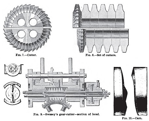
Fig. 7 is a side elevation of a bisected cutter; and Fig. 8 shows a series of six cutters, the end one being in elevation and the others in cross-section—these having cutting portions, which in cross-section represent the teeth of a rack, with the addition to the diameter of a given proportion of the pitch by which the clearance and fillets at the bottom of the teeth are made. If their cutting portions are formed of cycloids, then the whole set of gear-wheels cut with them will be of the epicycloidal or double-curve system. If they are formed simply of straight sides, then a set of involute or single-curve gears will be generated and cut, or their cutting portions may be composed of both straight lines and cycloids and produce Prof. McCord's recent system of gearing, which has composite teeth with the contours partly involute and partly epicycloidal.
All the cutters in a series are made exactly alike and interchangeable, the thickness of each or the distance from the center of one to the center of that adjoining being equal to the pitch of the gear to be cut. As indicated in Fig. 7, the two segments of a cutter are first made whole, with four holes an equal distance from the center, through which the rods pass that fasten them together. After the cutters are nearly completed they are bisected with a narrow tool, leaving two holes in each segment. Fig. 9 is a cross-section of the head, showing the mechanism for revolving and reciprocating the cutters. The rods which extend through the cutters serve not only to hold them firmly together but to revolve them, and at the same time act as slides for the reciprocating motion. The spindles on either side of the cutters, through which the rods extend, arc revolved independently and at the same speed by means of a parallel shaft, having a pinion at each end, which engages with a large gear on each spindle. By this means the four rods carrying the two cutter sections are revolved from each end. thus avoiding the torsional strain which would result if driven from one end only. The pair of rods for each section, after passing through one of the spindles, terminates in semi-cylindrical blocks. From each of these blocks a stud extends, on which is journaled a roll, engaging with a cam attached rigidly to the head. This cam is shown in Fig. 10, the working portions being made in the form of a screw-thread, which, if extended all the way around, would have a lead equal to the thickness or pitch of the cutter. As each section of the cutters engages with the wheel but three fourths of a revolution, the thread portion of the cam which carries the cutters forward extends only three fourths of its circumference, leaving the other one fourth for the reverse curves of the cam to bring the cutters back to their starting-point. Provision is made for adjusting one section of the cutters so as exactly to coincide with the other. The variation in the spacing from one tooth to another is reduced to a minimum, as the series of cutters act upon both sides of a number of teeth at the same time, and serve to average and eliminate any local inaccuracies in the division of the index and driving-gears; also to obviate any tendency to crowd the wheel from one side to the other. The endwise motion of the cutters and the revolving of the wheel at the pitch-line being exactly the same, the process of generating and cutting the teeth goes on continuously and uniformly around its entire periphery, so that one part is not heated more than another, but all the teeth are cut under exactly the same conditions, and when the revolving cutters have once passed across the face all the teeth in the gear are completed and given the correct form for each diameter of wheel; and as by the Willis theory all gears are cut to run into a rack, so by this process the same theory is put into practice and a rack is made to out correctly all gears. |
|
 1895 Warner & Swasey Co., Swasey's Gear Cutter
 1895 Warner & Swasey Co., Swasey's Gear Cutter Details
|
|