|
Title: |
1895 Article-Hugo Bilgram, Bevel Gear Cutter |
|
Source: |
Modern Mechanism 1895 pg 392-393 |
|
Insert Date: |
6/14/2011 11:03:03 AM |
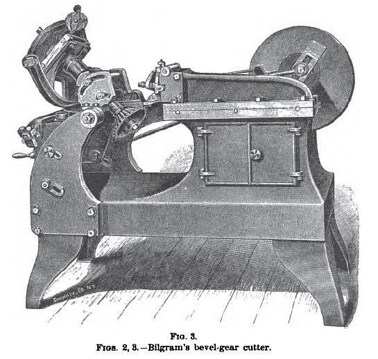
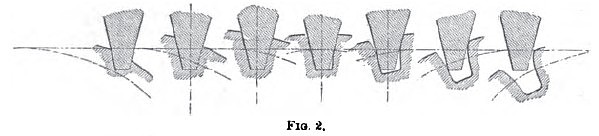
Bilgram’s Bevel-Gear Cutter is shown in Figs. 2 and 3. The principle of the machine is explained as follows: It is possible to make with any system of interchangeable gears a rack which will correctly gear with any wheel of the set. Any wheel that gears correctly with this rack must therefore also gear correctly with any other wheel of the set; and from this it follows that if any number of wheels are made to gear correctly with this rack, they must also gear correctly with one another. If the wheels were made of some soft material, say wax, the teeth could be formed by simply rolling the blank into the rack, care being taken that the pitch-line of the blank will roll on that of the rack without slip. The desirable clearance can be obtained by giving this rack just the converse of clearance. Gears are, however, made of material that can not be removed by pressure, and the process must therefore be modified. The teeth of the rack might be made of hardened steel, with sharp edges at the ends; and by giving them a lateral motion the material could be cut away instead of being pressed to one side. The diagram (Fig. 2) shows how the tooth of an involute rack would cut its way through the rolling blank, thus forming one of the spaces between two teeth.
This is, in fact, the process by which this gear-cutter accomplishes its work. The cutting tool represents one tooth of a rack pertaining to an interchangeable set of gears, and it obtains a reciprocating motion in the manner of a shaper-tool, while the blank receives a movement as though it were rolling on its pitch surface. In bevel-gears the tool representing the rack-tooth, while cutting, passes through the varying depths or pitches: therefore the straight line or involute rack-tooth is the only available one for this purpose. The tool, instead of running parallel with the pitch line, must run parallel with the bottom of the space. This will be more readily understood if it is considered that the rack of a bevel-gear is nothing else but a bevel-gear forming a pitch angle of 180° at the apex, or a flat, circular disk, with teeth converging from the circumference toward the center. The tool, in cutting, should follow the outline of the teeth of this imaginary plane-wheel: and it is evident, therefore, that only one side of the converging space can be formed correctly at a time. The machine, then, consists of two principal parts—the shaper, which holds and operates the tool, and what may be called the evolver, which holds and moves the blank. In order that the blank shall imitate the movement of a rolling cone, the axis must, in the first place, be moved in the manner of a conical pendulum. To accomplish this, the bearing of the arbor which carries the blank is secured in an inclined position between two uprights to a semicircular horizontal plate, which can be oscillated on a vertical axis passing through the apex of the blank. To complete the rolling action, the arbor must, in the second place, receive simultaneously the proper rotation, and this effect is produced in the machine by having a portion of a cone (corresponding with the pitch-cone of the blank) attached to the arbor, and held by two flexible steel bands stretched in opposite directions, thus preventing this cone from making any but a rolling motion when the arbor receives the before-described conical swinging motion. One end of each of the two bands, of course, is attached to the cone, while the other is attached to the framework of the evolver.
Mathematically speaking, a cone does not terminate at the apex, but is extended beyond, and thus consists of two opposite sides or surfaces meeting in the apex. Basing on this principle, the rolling cone above described is placed on the side of the apex opposite that on which the blank is placed, in order to avoid an interference with the tool.
The feed mechanism effects a slow intermittent movement of the semicircular plate which supports the inclined arbor, thereby producing a slowly progressing rolling of the blank while the reciprocating tool forces its way through the metal. The feed can tie reversed or disengaged altogether, permitting the blank to be rolled to the one or the other side by a hand-crank. The arbor carrying the blank can be rotated independent of the rolling cone by means of a worm-wheel, worm and index plate, which enables the blank to be presented to the cutting device at properly spaced divisions corresponding with the number of teeth of the desired wheel.
It is essential that the tool should be so adjusted that the lowest point of the cutting side should move exactly toward tho apex of the blank, and. in order to set the tool, a gauge is provided by which the tool can be adjusted. A distance-block is used between this gauge and the tool; this mode admits of a high degree of accuracy, since variations of distances can readily be detected by the touch when the eye ceases to discern.
When a wheel is to be cut out of the solid, the tool is at first adjusted at a slight distance from its correct position, and after each cut the feed-motion of the evolver causes the blank to slowly roll, and allows the tool to cut out the stock in the manner shown in the diagram. All spaces are now treated in the same manner by using the index device, whereupon the tool is properly adjusted for one and then for the other side, each adjustment being followed by a repetition of the process in order to finish both sides of the teeth.
In securing the blank to the arbor, great care must be exercised in placing its apex exactly in the center of the evolver. A special device enables the operator to gauge the distance of the ends of the teeth from the center of the evolver. and whenever this distance agrees with that calculated from the drawing, the apex of the blank is in its right place.
The inclination of the arbor which holds the blank is made adjustable, so as to adapt it to the angle of the desired gear. This adjustment must be exactly concentric with the center of the evolver—i. e.. the apex of the blank. The rolling cone is made detachable, in order that it may be replaced by such cones as correspond with the angle of the blank to be cut: but as the number of cones required would be unlimited, means have been devised to make a limited number of cones suffice.
The tool consists of a triangular bar of hardened steel, forming at the point an angle of 30°, 15° on each side, and held by a special holder. By grinding, it can lie more or less truncated to suit the pitch of the gear to be cut. By this form of tool a higher degree of accuracy is attainable than with tools having curved faces made to a gauge. The proper up-and-down and sidewise adjustment is effected by two slides working at right angles, and operated by screws. The clamp which fastens the tool-holder is so constructed that it also clamps the slides to the apron, securing the necessary stability. The box in which the apron works is made in parts, and the faces are turned true with the pin-holes, in order to get these faces
exactly at right angles with the pin. The latter is fast in the apron, and revolves in the two sides, in which it has taper fits that the wear may be taken up. A device for lifting the apron during the ret urn-stroke prevents the dragging of the tool.
The tool-bar is moved by a Whitworth quick-return motion, which is attached directly to the belt-pulley. A double counter-shaft connected by cone-pulleys is employed to change the speed, if a shorter or longer stroke is desired. |
|
 1895 Hugo Bilgram, Bevel Gear Cutter
 1895 Hugo Bilgram, Bevel Gear Profiles
|
|