|
Title: |
1895 Article-Fishkill Landing Machine Co, Corliss Steam Engine Valves |
|
Source: |
Modern Mechanism 1895 pg 313-314 |
|
Insert Date: |
6/14/2014 10:37:38 PM |
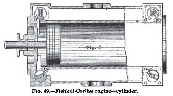
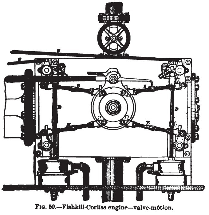
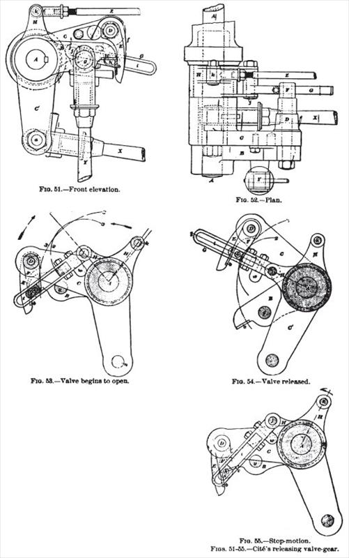
The Fishkill-Corliss Engine.—A sectional view of the cylinder of this engine is shown in Fig. 49. and a side view of the valve-motion is shown in Fig. 50. Cite's releasing valve-gear, as applied to this engine, is shown in the accompanying detailed cuts. Fig. 51 is a front elevation, and Fig. 52 is a plan. These show the valve-gear as it appears when engaged, and in the middle of its travel. Figs. 53, 54, and 55 are rear elevations. Fig. 53 shows the-parts in engagement at the moment the valve begins to open; Fig. 54 shows the position of the parts immediately after the valve has been released, and Fig. 55 illustrates the action of the stop-motion.
In nil the figures A represents the valve-stem and B the valve lever, which is secured to the end of the valve-stem by a feather and set-screw. C C is a double crank, which vibrates loosely on a sleeve around the valve stem, and is connected by an adjustable link-rod to the wrist-plate, from which it receives its motion. The end of the arm C carries a small rock-shaft D, which has a hook E fastened on one end. This hook is provided with a hardened steel catch-plate 6, which engages a similar plate c fastened on the end of the valve-lever B, and the hook is kept in place by a light spring /. On the end of the rock-shaft D, opposite the hook K, is fixed a forked crank F having a pin h on which is mounted a sliding-block s, and the outside of block s is fitted to move in a slot i of a link O. The link is mounted at and vibrates about a point j in one arm of a bell-crank H, and the bell crank oscillates upon a sleeve around the valve-stem. The other arm of the bell-crank H is connected by an adjustable rod 2 to the governor. By referring to Fig. 53, in which the double crank C C" is moved by the wrist-plate in the direction indicated by the arrow, and following the motion of the inner end of the block s, and also of the inner end of the slot i, it will be seen that these points will come together when the curved dotted lines 2 and 3 cross each other, and as the movement continues the block s will be pushed farther from the center of the valve-stem, and when the center line of the link shall be coincident with radial line 1. as shown in Fig. 54, the block will have been pushed so far outward that it will have slightly turned the small rock-shaft b, and moved the hook E enough to release the valve-lever B. Then the dash-pot will act and close the valve. At this moment of release, effected by the toggle-like action of the link, the pressure on the bell-crank H, caused by the liberation, will be exerted in a radial line from the center of the slot through the point/to the center of the valve-stem or the stand which supports it. and during the entire movement of the hook E there will be no appreciable strain to turn the bell-crank H. and consequently there will be no strain to disturb the normal action of the governor. As the position of the bell-crank His controlled by the governor, any change in the height of the governor will cause a change in the position of the point, and a corresponding change in the time of release. The action of the automatic safety-stop motion is illustrated by Figs. 53 and 55. Fig. 53 shows the position of the various parts when the engine is at its lowest normal speed, and the hook E is at. the point of engagement with the valve lever B. The lower side of the link 67 is provided with an adjustable embossment u, which, in the position shown, is just clear from the hub of the bell-crank H. Now, should the governor belt be broken, or if from any other cause the governor-balls should fall below this point, the bell-crank M will be moved in the direction indicated by the arrow in Fig. 55, the embossment w will be brought against the hub of the bell crank, and the continued movement of the bell-crank will cause the embossment to act us a fulcrum, and the lower side of the slot I will cause the pin h in the forked crank F to move outward, or from the center of valve-stem A. This will carry the hook E outward so far that it will not engage with the valve-lever B, and the valve will remain closed. In connection with the above, an attachment is placed on the governor column, by means of which the action of the stop-motion may be suspended or made operative at any time by the engineer, and when suspended the engine can be stopped and started in t he usual way. |
|
 1895 Fishkill Landing Machine Co, Corliss Steam Engine Cylinder1895 Article-Fishkill Landing Machine
 1895 Fishkill Landing Machine Co, Corliss Steam Engine Valve Motion
 1895 Fishkill Landing Machine Co, Corliss Steam Engine Valve Linkage
|
|