|
Title: |
1895 Article-Stearns Manufacturing Co., Woodbury Steam Engine |
|
Source: |
Modern Mechanism 1895 pg 301-302 |
|
Insert Date: |
6/8/2011 9:48:44 PM |
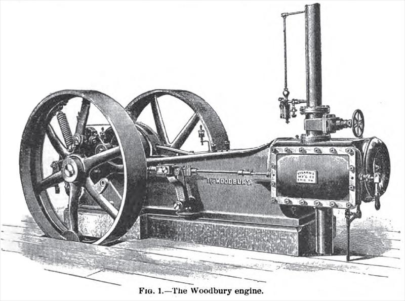
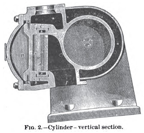
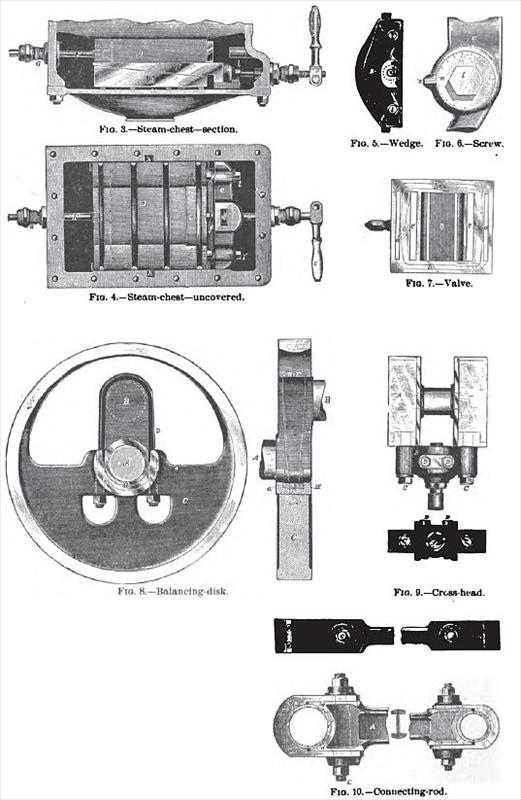
The Woodbury Engine is shown in perspective in Fig. 1. Fig. 2 is a vertical section through the cylinder and valve. Fig. 3 is a horizontal section through the steam-chest above the top of the valve. Fig. 4 shows the steam-chest with cover removed, exhibiting the back of the relief-plate and wedge. Fig. 5 is an end view of the relief-plate and wedge. Fig. (1 is an enlarged view of the upper adjusting screw; and Fig. 7 is a back view of the valve.
Referring to Fig. 2, steam-pressure is eliminated from the valve A by the relief-plate B on the back, which is supported against steam-pressure at top and bottom by a forked or double wedge 6* whose length is about equal to that of the relief-plate. It is obvious that a longitudinal movement of the wedges inward will force the relief-plate away from the valve, and the outward movement of the wedges will let it down toward the valve. The movement of the wedges, and consequent adjustment of relief-plate, is accomplished by the two adjusting screws 11' (Fig. 8), which fit loosely through the cross-piece of wedge and are tapped into the relief-plate. The collars m, which form part of adjusting screws, are notched on their peripheries, as shown in Fig. 6, and a notch n is made on the wedge opposite each screw. The collar has 100 notches, and therefore admits of a definite degree of adjustment. The adjusting screw has 10 threads per in., and the taper of wedges is 1 in. in 10. One notch on the collar, therefore, representing 1/100 of a turn, moves the wedge lengthwise 1/1,000 of an in., and the relief-plate toward or from the valve 1/10,000 of an in., corresponding to 1/20,000 of an in. on each face of the valve. The passage k at the bottom of the chest allows a circulation of steam under the ledge, insuring equal temperatures for ledges ii. The screw D, which is operated from the outside by the handle E, is also used as a means of moving the wedges inward and throwing off the relief plate; but the plate can not be let down farther than the adjustment allows, as the wedges can not be drawn back farther than the collars m of screws I V (Fig. 6). The amount of inward movement is regulated by the screw/ (Fig. 4) which forms the stop for the inward movement of the wedges. This screw taps into the relief plate, and against its head the cross-piece of the wedge strikes. When the handle E is turned to the left as far as it will go, the wedges are back against the collars and are in proper working position; when, on the contrary, the handle is moved to the right, the screw which works through the stuffing-box forces the wedges inward and throws off the relief-plate. About one half turn of the handle is all that is necessary. The purpose of this handle and screw is to afford a means of separating the valve-faces from seats in case they tend to adhere together lifter engine has been standing for some time. The valve A (Fig. 8) besides taking steam at the ends, has supplemental admission ports a a (Fig. 7) which are connected at top and bottom by passages b b'. The steam is entering cylinder-port directly past the end of the valve, and also through the cavity in the relief-plate into port a'. Steam is at the same time entering supplemental port a at opposite end at two points, and traveling through the horizontal passages into port a' and cylinder-port. The admission, therefore, takes place at four points at the same time, and, as the ports are very large, the nearest approach to boiler-pressure is reached, and the usual loss between boiler and cylinder reduced. A double exhaust is also used.
Fig. 8 shows the method of attaching the counter-weighted disks to the cranks for the purpose of balancing the reciprocating parts.
Fig. 9 shows the cross-head in top and end view, the piston-rod being in section.
The construction of the main connecting-rod is shown in Fig. 10. |
|
 1895 Stearns Manufacturing Co., Woodbury Steam Engine
 1895 Stearns Manufacturing Co., Woodbury Steam Engine Cylinder
 1895 Stearns Manufacturing Co., Woodbury Steam Engine Parts
|
|