|
Title: |
1895 Article-Electric Mfg. & Gas Engiine Co., Rollason Gas Engine |
|
Source: |
Modern Mechanism 1895 pgs 268-269 |
|
Insert Date: |
11/9/2012 7:52:10 PM |
The Rollason Gas-Engine, made by tho Electric Manufacturing and Gas-Engine Co., Greenbush, N. Y., is of the three-cycle type—i. e., the crank-shaft makes three revolutions for each explosion of gas, and the governor acts to regulate the amount of gas supplied for each explosion, from the maximum down to a point at which it can no longer be used economically, when the supply is cut off entirely, and no explosion takes place until a sufficient diminution of speed occurs.
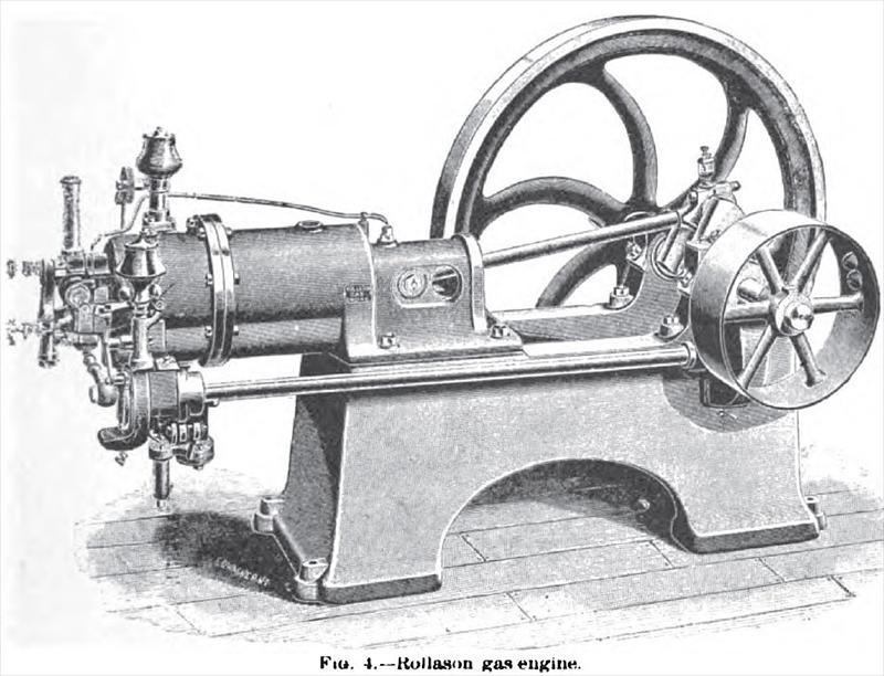
The operation of the engine is as follows: Supposing an explosion to have just taken place, the piston, under the impetus given, makes a forward stroke; the exhaust-valve is then opened and the piston returns, expelling the larger portion of the products of combustion. During the next forward stroke a scavenger charge of air is drawn into the cylinder, and on return stroke is forced out through the exhaust, thus entirely clearing the cylinder and explosion chamber. On the fifth stroke a combustible charge of gas and air is drawn in, compressed ready for ignition by the sixth or return stroke; thus the cycle is completed. At the commencement of the seventh stroke an explosion again takes place, and so on. The construction of this engine is shown in Figs. 3 and 4. The connecting-rod is pivoted directly to the piston, which has a guiding trunk. The cylinder is surrounded with a water jacket, which extends around the combustion-chamber up to the rear valve-face. The chamber itself is isolated from the influence of the jacket by an annular space, which is filled with a non-conductor. A side-shaft, revolving at one third the rate of the crank-shaft, works the slide-valve at the back of the cylinder by means of a connecting-rod and a rocking-beam. The slide-valve is shown in the horizontal section of the cylinder (Fig. 3), and is formed with ports through which the supply of air and gas is admitted. The gas-valve is raised at the proper instant by a cam, which is shaped to proportion the influx of gas to the speed of the piston. The amount of gas admitted is regulated by the governor, which is driven by the side-shaft. The governor is connected by a rod to the valve, and as it rises it throttles the supply of gas to make it When the dilution of the charge has been carried as far as is economical, the gas is cut off entirely. A second lever connected with the governor carries a counter-weight, and by altering the position of this weight the speed of the engine can be varied. This lever can be readily put in or out of connection with the governor, its principal object being to enable the engine to be slowed down when not actually doing work. When combustible mixture is to be admitted to the cylinder, the valve-ports coincide with admission, gas, and air inlets, the gas-valve is opened and the charge flows in, following the outward movement of the piston. The first portion of the combustible gases taken in flows down the center of the cylinder until the piston stops, and then it divides and flows back along the walls. This portion, which is diluted with the air in the combustion-chamber, is congregated round the tiring-port, while the richer part of the charge is situated next the piston. The weaker part is ignited first, and the velocity of combustion increases as it approaches the richer part. Prof. A. B. W. Kennedy, of London, made in 1888 a test of this engine under varying conditions, and his report of its performance is published in Engineering, May 4th and 11th of that year. The results as to its efficiency are summed up as follows, being the average of four experiments:
Percentage of whole heat of combustion turned into work 19.6%
Percentage rejected in jacket water 33%
Percentage rejected in exhaust 43.1%
Percentage rejected in blank charge and unaccounted for 4.3%
Total 100.0%
The mechanical efficiency of the engine on net indicated horse-power during the trials ranged from 86-1 to 90-8; and the consumption of gas per indicated horse-power per hour 20-67 ft. to 21-68 ft. |
|
 1895 Electric Mfg. & Gas Engiine Co., Rollason Gas Engine
|
|