|
Title: |
1855 article on Brown's double gang steam sawmill |
|
Source: |
Scientific American. / Volume 11, Issue 8 (Nov 3, 1855), p. 60 |
|
Insert Date: |
8/21/2003 9:57:58 PM |
Article text:
IMPROVED GANG SAW MILL.
The annexed figures are a front view, fig. 1 and a side view, fig. 2, of an improvement in Gang Saw Mills, for which a patent was obtained by Isaac Brown, of Baltimore, Md., on the 19th July, 1853. An illustration of the single saw mill was given in Vol. 10, No.37, page 292, of the SCIENTIFIC AMERICAN.
A A are the fender posts, to which the cylinders are firmly bolted, forming the bed plates, also the slides for the cross head or saw sash to work against. They are firmly secured together at the top and near the bottom of the saw sash, and bolted down to heavy foundation timbers, which makes the whole of the combined mill and engine very firm and substantial. B represents the saw sash with a center support, allowing it to be much lighter and of sufficient strength to carry two gangs of fifty saws at one time. One space only is shown, filled with saws, whilst the other space shows the position of the log without the saws, with the rollers for forwarding the logs to the saws when in operation. This saw sash is also the cross head of the engine, which receives its motion from the piston rods on each side. The pressure is equally distributed, and each part bears its due proportion of strain. There is no part overloaded, or liable to heat. The pistons, connecting rods, and fly-wheels thus operating the saw sash, the weight of which and the saws are lifted by the power of the steam in the downward stroke, adds power to be expended to cut into the timber, thus exerting the greatest force at the moment required, and that in the saw sash itself without having to be transmitted through belts, gearing, or connecting rods, at a great loss by friction, wear and tear, &c.
C are steam cylinders of the usual form, with stuffing boxes and glands at each end; the steam chests are in the angle inside the frame. D are the connecting rods or pitmans. E E are fly wheels; they are turned and used as pulleys for operating timber hauling apparatus, pumps, edging saws, and any other purpose required for the operations of the mill. F F are crank pins, firmly secured in the fly wheels. G G are piston rods passing through both heads of the cylinders, and by the glands and packing are guided to work true, with the ends resting on bearing surfaces near the point of connecting at the top, and at H on the lower part of the saw sash. The piston rods are made so short that when expanded by steam they will fill the space between these two points of bearing, allowing them to work free and unrestrained, and effectually preventing their working out of line or allowing the pistons to revolve within the cylinders, thus securing them from cutting or unequal wearing. I is the engine shaft, performing the office of crank shaft, and is firmly secured in pedestal bearings, resting on the engine frame, thus securing the whole substantially together. J is the exhaust pipe conducting the steam to the heater below, and heating the water to be forced into the boilers from the pumps. K is a rock shaft, giving the desired motion by means of proper connections with the eccentric, L, to the valves in each steam chest. M is an eccentric giving motion to the feeding apparatus by means of the rock shaft and eccentric rod, 0; and it is so arranged that the speed of the cutting for either gang of saws may be adjusted at pleasure, or the motion of one or the other reversed, as may be desired. N are ratchet stock and gear wheels giving motion to the feed rolls, and carrying the logs forward to the saws. P P are feed rolls, with teeth arranged to be taken out when required, for sawing flat sided timber, or when it may have been sided down by one set of the gang saws and requires further sawing to make square dimension timber cut to order, such as deals, and other sizes. Q represents top pressure rolls, arranged with an adjustable lever to accommodate the varying sizes of logs; they have teeth for holding round logs steady, and may be taken out when sawing flat timber. R R are trucks moving on rail tracks, and so arranged with right and left screws to tighten the logs, hold them firmly, and guide them in the proper direction while being sawed. In operation, as the logs pass to the saws, one truck is disengaged and backed to receive another log, by which means a continuous cut is kept on the timber while the saws are in order, or until they need adjusting or sharpening, which is generally performed once a day, and before starting in the morning. S S are levers, to which the weights are attached to give the pressure required to hold the timber while being sawed. T is a pulley for using the surplus power for any other purpose required. U U are pumps, so arranged that one is kept in reserve, allowing the bringing of it into use in the case of the other failing to work from any cause. In pumping up to the boilers by hand power, both pumps are used, and the log wheel gearing serves as a well arranged capstan, whereby the pumps can be worked, by bars, with great facility; the large pulley X, acts as a fly wheel, giving steadiness to the stroke of the pump. V is an upright shaft, around which the chain winds to haul up the timber from either direction to be sawed. W is a bevel wheel on the lower end of the timber-hauling shaft. It is driven by a pinion upon the pump shaft, and is arranged with a clutch to start or stop at pleasure. The pulley driven from the fly wheel gives full power to haul up the timber as fast as it is required for sawing. Y is a sheave on the engine shaft, by which scrapers are driven to remove the sawdust near to the front, to be shoveled under the boilers for generating steam. Z is a substantial timber frame around the engine, to which is secured the feed and pressure roller fixtures, and supporting the end of the rail tracks for the trucks. & are the foundation timbers upon which the engine and mill fixtures stand, the same being well locked by keys, and bolted together.
The steam boilers are not shown, as their location can be varied as circumstances may require. The wrought and cast iron in this sawing machine amount to about fifteen tuns, and is of the most substantial construction. A first class saw mill of this kind is covered with a sheet iron roof to secure it from fire. We have been informed that the cost of a mill of this kind complete, with boilers and all, does not exceed $500 for each 1000 feet of lumber it will saw in ten hours. The claims of this patent will be found on page 366, Vol. 8, SCIENTIFIC AMERICAN. It has never before been so illustrated and presented to the consideration of the public. - Every improvement in saw mills is of great importance to our country.
More information respecting it may be obtained by letter addressed to Mr. Brown, at Baltimore. |
|
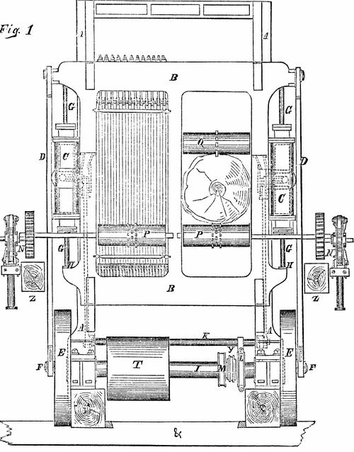 Fig. 1, Brown's double gang steam saw mill
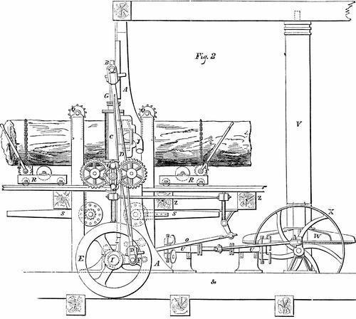 Fig. 2, Brown's double gang steam saw mill
|
|