|
Title: |
1855 article on Brown's steam sawmill |
|
Source: |
Scientific American. / Volume 10, Issue 37 (May 26, 1855), p. 292 |
|
Insert Date: |
8/21/2003 10:34:36 AM |
Article text:
IMPROVEMENT IN SAW MILLS
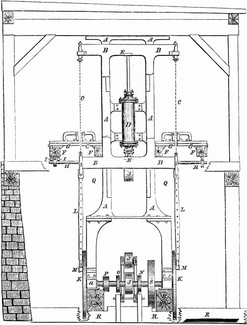
The annexed figure is a front view of an improvement in saw mills, for which a patent was obtained by Isaac Brown, of Baltimore, Md., on the 19th of July, 1853, but which has never before been thus brought before the public. Every improvement in saw mills interests a very large class of our people; the great majority of which, we believe, are readers of the SCIENTIFIC AMERICAN.
A is the engine frame, also answering for fender posts to saw mill. B are cross-heads, also saw gate sliding against fender posts. C are saws strained between the cross heads or in saw gate. D is the steam cylinder, firmly bolted between the fender posts, with piston rod extending through both heads of the cylinder, resting between top and bottom cross girts of the saw gate in substantial bearing surfaces, E, leaving the ends of the piston rod unrestrained to work in line with the cylinder, and with freedom to the piston, to revolve in the cylinder, allowing the surfaces of the packing rings and cylinder to adjust and wear more smoothly and prevent cutting, than can be obtained when the piston is rigidly fixed in the cross head. The steam chest and valve motion are of the usual construction. F is the end view of carriage with the head blocks, G, and dogs to secure the logs while being sawed. H are racks and pinions to give the desired motion to the carriage. I are rolls under the carriage, and guides by the segments to secure a straight line for the carriage. J are pulleys so arranged in connection with clutches, tightening pulley, and belt, to back the carriages for either saws. K are crank fly wheels for the engine regulating the motion and stroke of the saws by the connecting rods, L, secured firmly with the lower saw buckles and crank pin, M, thereby giving firmness to the cut of the saws by the momentum of the fly wheel. N is the eccentric to give motion to the valve in the steam chest (not shown.) O is the eccentric to give motion to a rock shaft for feeding the carriages forward with the logs to the saws, and readily adjusted while the saws are cutting to give any required feed to either saw. P is the pulley for pump to supply boilers in the usual way. Q is the stand and pedestal to support engine frame, fly wheels, and shaft. R are foundation timbers well bolted together. S is the pulley to give motion to any machinery desirable, as circular saws to saw lath, pailings, edging boards, as well as for small portable mills for grinding grain, or any purpose, as the engine will work as efficiently without working the upright saws as any other engine of the same boiler power.
The best site to erect this mill upon is a sloping ground, with a wall on the side next to the high side, to keep back the ground; and excavating a foundation on the lower side giving sufficient elevation for room to work under the mill and get out the sawdust, chips, and wastage at a convenient elevation to the mouth of the boiler furnace, to use as fuel.
The logs on the elevated ground above the mill can be readily put on the carriages for sawing, and the lumber turned off at the lower side, thereby avoiding much labor of handling heavy lumber when the locations are not well selected.
A space ten feet square in the saw pit is sufficiently large for the machinery below, and a width of room above, say fourteen feet wide by double length of the timber desired to be sawed, and one story of eight feet high, with sufficient covering to keep out the weather, is all that is desired. The wall under and outside of the boiler walls will answer to support the machinery. This mill will do as much work as any other with the same number of saws driven in a saw gate. As much power may be given to the saws as will force them into the wood at each cut, as far as the saws are able to withstand the resistance against them. As regards keeping all the parts in order, this depends on the workmanship of the machine itself, and the parties using it. The principle of the construction of this mill, Mr. Brown says, renders it less liable to get out of order (it having no more than one half the number of parts) than other steam mills, while, at the same time, it has an important feature in the engine itself that avoids one of the greatest difficulties in sawing, viz: getting out of line and cutting the cylinder, an evil to which all other engines are liable without the greatest care.
A less number of workmen can keep it in operation, and do as much work. The engine is under the control of the sawyer, who is also the engineer, and regulates the speed to suit the work; and he alone can perform all the work of sawing after the logs are put on without stopping the mill, thereby needing ordinary hands only for handling lumber, cleaning up the sawdust and wastage into the furnace, to keep up the steam.
This mill can be completed at the machine shop, requiring not more than ten days to put it up on its foundations, they being prepared. He is now constructing double gangs carrying fifty saws, cutting at the same time, with rollers and feed power, making a continuous cut at the timber, the logs following each other through the gangs, and cutting up the lumber to any dimensions, with rapidity and accuracy, thereby making a most substantial machine for sawing.
Mr. Brown has devoted thirty years to the working of steam saw mills, and will superintend the construction of his mills, if required, until they are in satisfactory operation.
More information may be obtained by letter addressed to him at Baltimore. |
|
 Brown's Improved Saw Mill
|
|