|
Title: |
1890 Article-Watertown Steam Engine Co., Automatic Steam Engine |
|
Source: |
The Steam User 1890 pg 80 |
|
Insert Date: |
4/20/2011 9:13:11 AM |
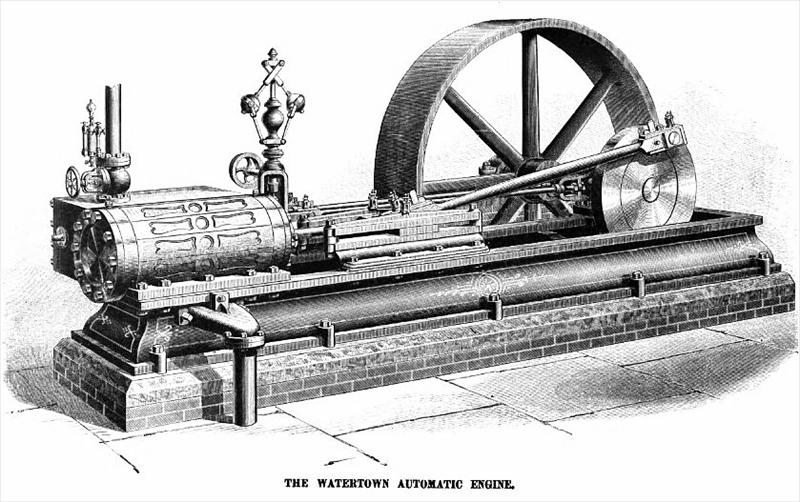
The engraving on the opposite page represents a Watertown Automatic Engine. The bed of the engine, as will be seen, is very solid and heavy. It is what is known as a " box bed," and has heavy flanges lying close to the foundation for its whole length. It is held by a double line of anchor bolts throughout the entire distance.
This box bed is cast in one piece, is carefully and accurately planed on both top and bottom. It holds bearings, guide, and cylinder in perfect line, renders adjustment of them easy, and permits either to be removed or altered with the least possible inconvenience. On the lower flange of the frame are cast heavy lugs designed to receive the foundation bolts, which are distributed through its length. The upper part of the frame on the cylinder end is cut down so that the cylinder may set into the frame, bringing the centre line of the engine as low as possible.
The cylinder casting is very heavy, not only affording opportunity to rebore the cylinder, should wear make it necessary, but also by the great mass of iron retaining the heat imparted to it by the steam, and preventing loss in economy by repeated heating and cooling. The cylinder is further supplied with a jacket of hot air formed by close fitting cast-iron panels secured by neat brass bands. Flanges are broad and heavy.
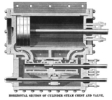
The steam-chest extends nearly the entire length of the cylinder, bringing the ports as near as possible to the end of the stroke, making steam passages very short and reducing clearance as much as possible. It has very broad ports opening nearly the whole height of the cylinder and allowing the water of condensation to escape readily from the cylinder.
The valve used is of the slide pattern, which is so effective for opening and closing the ports of quick-moving engines. It is simple and easily fitted. It admits of the least loss, opens and closes the valves with the quickest motion, and is the least liable of all valves to become leaky from use. Of the several forms of valve, the flat is preferable to the curved from the greater facility of accurate fitting, and the more equal wear of two planes as compared with cylindrical surfaces. With a flat valve, wear only makes a tighter fit. A flat valve is always to be preferred unless some peculiarity of cut-off prevents its use. Many attempts have been made to produce a balanced slide valve. Scores of patents have been taken out, of more or less complexity, but none have stood the test of successive years of work, the great difficulty being the waste and leakage sure to result from a little wear. It is especially difficult to detect this waste.
It will be observed that the main valve is a regular three-ported D valve, controlling the admission of steam as in a plain slide-valve engine. It has the proper lap, lead, and exhaust closure, which it retains throughout the stroke independent of the point of cut-off. The steam passages pass through the main valve, taking the diagonal form on its back. Riding on the back of the main valve is the cut-off valve. On the back of this cut-off valve is a rack engaging a pinion on the cut-off rod, which is operated by a second and independent eccentric on the main shaft. This eccentric is set without lead, and follows the action of the main eccentric, the cut-off valve following the movement of the main valve.
It will be readily seen that if the rod carrying the cut-off valve is rotated in one direction, the cut-off valve itself will be raised by the action of the pinion and rack, thereby covering the oblique ports on the main valve to a greater or less extent. Motion in a contrary direction lowers the valve and permits uninterrupted admission of steam throughout the entire area of the ports.
The governor which determines the cut-off is, next to the valves, the most important part of the whole economy of the engine. By carrying the arms across the centre of the governor axis brings the point of suspension very low, making the governor very sensitive, and securing prompt regulation within the least possible number of revolutions.
Attached to the base of the governor is an indicator showing at a glance the point at which the engine may be cutting off. By watching this indicator one can determine instantly not only the point of cut-off and the work the engine is doing, but can also observe the variations in the amount of load as it is thrown on or off. It is quite possible by means of this indicator to watch changes in the load from nothing up to the full power of the engine, involving a change in the cut-off from the least point possible to the full stroke, while the speed of the governor does not alter enough to be in the least degree perceptible. At the foot of the governor stem is attached an adjustable counter-balance, equalizing the weight of the balls, reducing the labor of actuation to a minimum, and permitting so close an adjustment that the variation of the speed is confined within a very small compass. Moreover, by this weight it is possible to adjust the speed of the engine to a greater or less number of revolutions should circumstances make it necessary.
There are no complications of cams, levers, rock-shafts, or tripping gears. It has been the aim to make this engine as simple as possible. The manufacturers have reduced to the fewest number of parts the mechanism connected with the cut-off. In the majority of cut-off engines in the class with which we have drawn a comparison, the cut-off is effected by a number of tappets, cams, or other devices, which are hooked on to the valve and released in each stroke. The cut-off valve is not directly connected with the eccentric, but takes its motion entirely through the intervention of this complicated system of tappets, cams, and springs. The large number of parts necessary and the increased liability to wear or damage result in a complicated piece of mechanism, and necessitate the services of a very superior engineer, and involve very great loss if out of order or improperly cared for. The cut-off used is so easily comprehended and cared for by any engineer of ordinary intelligence that it is almost impossible to get out of order.
It is claimed for this cut-off a range of the whole length of the stroke; from the admission of steam barely sufficient to meet the friction of the engine up to the full length of the stroke. This is of particular advantage in the case of any extraordinary and unexpectedly heavy load; or on the occasion of any especially low pressure, the point of cut-off and of exhaust being entirely independent of each other. This results from the use of separate and independent valves to operate the cut-off. It gives a cut-off perfect in operation, varying the point of cut-off not only without changing lead, but also without changing exhaust closure, as most of the engines of this class are of necessity compelled to do.
(These engines are manufactured by the Watertown Steam-Engine Company, Watertown, New York. Represented by E. P. Hampson & Co., 36 Cortlandt St., New York City.) |
|
 1890 Watertown Steam Engine Co., Automatic Steam Engine
 1890 Watertown Steam Engine Co., Automatic Steam Engine (Steam Chest & Valve)
|
|