|
Title: |
1890 Article-Watts, Campbell & Co., Tandem Corliss Steam Engine |
|
Source: |
The Steam User 1890 pg 49 & Modern Mechanism 1895 pgs 322, 324 |
|
Insert Date: |
6/12/2011 12:36:42 PM |
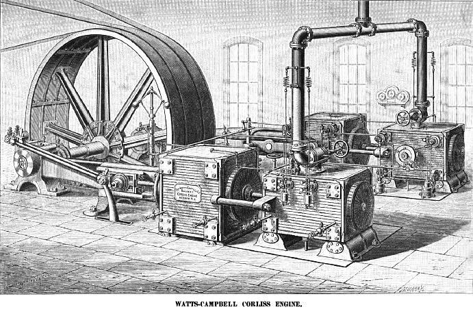
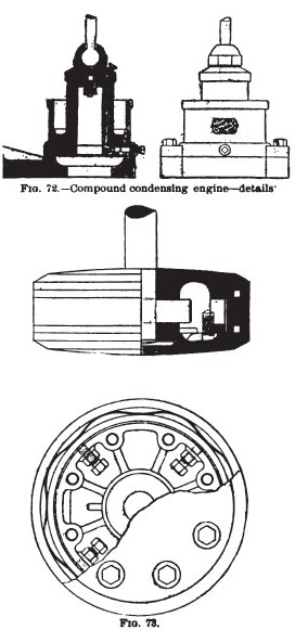
The Watts-Campbell Compound-Condensing Engine.—The full-page engraving represents a pair of engines recently put in the Shrewsbury Mills, at East Newark, N. J., by the Watts-Campbell Co., of Newark, N. J. The engines are tandem-compound, coupled to the shaft at right angles. The high-pressure cylinders are 20 in. diameter and the low pressure 36 in.; stroke of pistons, 48 in. The engines run at a speed of 64 revolutions per min. Both the high and low pressure cylinders are steam-jacketed, the former with steam direct from the boiler and the latter with the exhaust steam from the high-pressure cylinders. The exhaust from the high-pressure cylinder passes down through the legs to the receiver, which is cast as part of the low-pressure cylinder and includes the jacket-space of that cylinder. From the low-pressure cylinder the exhaust goes through a large rectangular passage to the condenser, which is situated midway between the two low-pressure cylinders. A small pump returns the water of condensation from the jackets to the boilers. But one air-pump is employed, which is driven by a return rod from one of the crank-pins. The main shaft is 16 in. diameter at the center or wheel fit, and 13 in. at the journals. The band fly-wheel is 25 ft. in diameter, built up in ten segments. It has a face of 6 ft. 2 in., turned for two 28-in. belts and one 10-in. belt. The weight of the fly-wheel is 73,000 lbs. The valve-gear is of the Corliss type, with modifications that have been introduced by the Watts-Campbell Co. The speed is "controlled by means of a small fly-ball governor, running at very moderate speed the governor controls admission by eight steam-valves with great precision, without the use of a dash-pot or equivalent attachment to prevent fluctuation. This absence of shock to the governor is mainly due to the action of the releasing gear. Fig. 72 shows the dash-pot used in the Watts-Campbell Corliss engines. The vacuum which serves to close the valve is maintained in the chamber above the central post. As the piston descends, closing the steam-valve, any small quantity of air that may have found its way into this chamber is displaced through the automatic valve shown in the top of post. The cushioning is accomplished in the annular chamber at the bottom. The piston in falling is first partially obstructed in the tapered upper part of the annular chamber; then, as it passes this tapered portion, it is more completely resisted, the only escape for the imprisoned air being such as is provided by the adjusting screw. By means of this screw any desired adjustment of cushion can be made, interposed leathers preventing the parts from striking metal to metal while making such adjustment, or at any time while in operation.
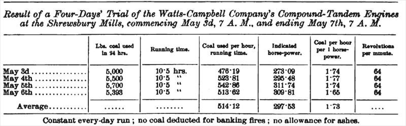
The piston and piston packing used in these engines are shown in Pig. 73. The weight rests upon the center ring, to which the piston and follower are securely attached. When, by wear of the bottom of the center ring and of the cylinder, the piston gets below the center, it can be accurately centered by means of the adjusting screws. This is considered by the builders essential in a horizontal engine, in which, owing to gravity, the bottom of piston and cylinder will be subjected to somewhat the most wear. The center ring carries the weight of the piston, and protects the head and follower from wear. By the Watts-Campbell method of turning the center ring the lower or bearing part is made to exactly fit the bore of the cylinder, the ring being turned out of round to give the requisite clearance. This gives full bearing surface from the start. The packing consists of two small rings, one at either edge of the center ring. These are turned somewhat larger than the bore of the cylinder, then cut and halved together at the joints. When in place they keep in easy contact with the cylinder, without undue friction, compensating for wear by their own elasticity. Light springs are supplied, as shown, which assist in keeping the rings in contact with the cylinder until they are worn out. The governor is connected with a cross-shaft from which small single rods extend to the releasing mechanism of the four cylinders, doing away with the use of the double rods usually employed. In compound engines the connecting rods are six cranks in length. The piston-rods have two different diameters in their length, the difference being sufficient to afford a taper seat for the low-pressure pistons. These pistons are held in place by a key. By disconnecting the rod at the cross-head and moving the low-pressure piston hack into the space between the two cylinders the key can be removed: then, by moving the rod forward, the piston can be removed. A noticeable feature in these engines is the fastenings which hold the bed-plates to the pillow-block. In addition to the usual bolts, recesses are east in the front side of the pillow block and in the front side of the frame against the pillow-block, and a wrought-iron link Constant every day run; no coal deducted for banking fires; no allowance for ashes. The table above shows the result of a recent test of a pair of these engines, guaranteed to develop 700 indicated horse-power per hour. Upon starting the engines it was found that it would not, at least for some time, be practicable to load them to more than about 300 horse-power; it was then concluded to disconnect one of the pair and test the other, the builders of the engines waiving the right to steam of 110 lbs. steam pressure, and using but 80 lbs.; two boilers only were used. While the engine was run only through the ordinary working hours— 10½—all the coal used during the 24 hours was charged against it; this included coal for banking fires, getting up steam in the morning, etc. The test was continued for 4 days— 96 hours—a large number of diagrams being taken from which to compute the power. |
|
 1890 Watts, Campbell & Co., Tandem Corliss Steam Engine
 1895 Watts, Campbell & Co., Tandem Corliss Steam Engine Details
 1895 Watts, Campbell & Co., Tandem Corliss Steam Engine Trial
|
|