|
Title: |
1890 Article-M. C. Bullock Mfg. Co., Corliss Steam Engine |
|
Source: |
The Steam User 1890 pgs 1 & 3 |
|
Insert Date: |
4/12/2011 3:20:36 PM |
THE FRAME OF THE BULLOCK-CORLISS ENGINE.
By referring to Figures 4 and 5, it is seen that there is combined the strengths of a T beam and a channel beam in a channel beam with extra wide top and bottom members, thus producing exceptional strength. All up-and-down strains, due to the thrust of the connecting-rod, are resisted by the top and bottom members, placed as far from the neutral line of the girder as possible, assisted by the broad front web, which is placed as close as possible to the centre of strain. These up and down strains are not the severest the frame receives, because of the support of the centre foot, described hereafter. The severest strains are tension and compression and the side strains, due to the centre of the pillow block being out of line with the engine cylinder. This latter strain is resisted by the two wide top and bottom members of the beam, which in themselves have the greatest amount of metal where the most liable to spring, u e., where the reach joins the guide tube.
The -whole frame combines extraordinary stiffness with symmetry.
The connecting-rod, forged in one piece, of best scrap, is of novel and careful design. The cross-head end has the well known wedge-block adjustment, with provisions for putting shims on straight faces.
The crank-pin end is the reliable marine type. The whole rod combines strength, rigidity, uniformity of metal distribution, and lightness.
The cross-head has its pin in the central plane of the cross-head shoes, thus throwing no bending strains on the piston-rod. The shoes are of such unusual size that the pressure per square inch (due to the thrust of the connecting-rod) is very low, avoiding all heating, cutting, and excessive wear.
The valve motion levers are all of oval section of ample strength. The knock-off or trip device is of the hook form. It releases with the same pressure at any point of cut-off, because the leverage is constant, thus giving the governor the same slight resistance at all positions. The catch and hook have each a square, hardened steel block, both of exactly the same size, and each having eight edges alike for wear, so that when one edge is worn another may be brought in use, or the blocks may be interchanged. This is important for engines wherever placed, but particularly so with engines in regions inaccessible to shops where such work is done and fully understood.
The governor is of new and careful design, clearly shown in the general views of the engine. It is in one sense a weight governor, in that the centrifugal force of the balls is balanced by a weight, which remains constant for all times and all positions, and not by a spring, which varies according to the amount it is strained, which deteriorates with age, and which is liable to break. The action of the balls is peculiar, because the long arm is attached to the sliding sleeve. As the balls fly out, this sleeve rises and, in combination with the links at the top, tends to depress the balls. The result is, the balls fly out in nearly a horizontal plane. This action, calculations and practice prove to be the best and most delicate.
A dash pot is used, not because absolutely necessary, but because it is better on any design of governor to maintain the engine at a uniform speed by a uniform cut-off, and not by the average of varying cut-offs, where the governor, not controlled by a dash pot, is liable to sudden changes during one revolution of the engine.
The governor does not have to run at an excessive speed, and is therefore longer lived than one running faster. It runs from 120 to 150 revolutions, according to size; for the governor is proportioned to suit the engine it is used with, having several sizes of governors, and not having one size governor on all sizes of engines, as is often done.
The eccentric and strap are of improved form. Where the eccentric strap joins the eccentric rod, it is carried forward and stiffened, thus preventing the tremble so often noticed in eccentric rods. On both the eccentric and hook-rod ends, at the carrier arm, are screwed brass heads, adjusted by wedge and bolt, giving perfect adjustment for wear and for lengths of rods.
Several other features are worthy of mention, but space will not permit further description. These engines are also made in compound and triple expansion type, from 200 to 1,000 horse-power in tandem form or arranged side by side. (Manufactured by the M. C. Bullock Manufacturing Co., Chicago, 111.) |
|
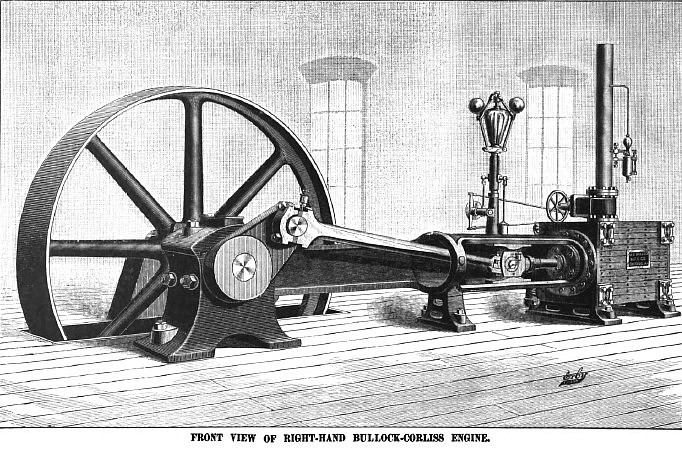 1890 M. C. Bullock Mfg. Co., Corliss Steam Engine (Front View)
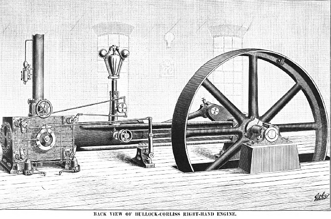 1890 M. C. Bullock Mfg. Co., Corliss Steam Engine (Back View)
|
|