|
Title: |
1890 Article-Lane & Bodley, Tandem Compound Corliss Steam Engine |
|
Source: |
The Steam User 1890 pgs xvi & xvii |
|
Insert Date: |
4/2/2011 3:21:08 PM |
The valves are of the original Corliss type with cylindrical ends of greater lengths than usual (the surface on our 14-inch being as large as on some makes of 18inch engine). The stems are of phosphor bronze, extending clear through the length of the valve with a bearing in the back bonnet. Spiral springs are let into the blades of the valve stems to allow some compensation. This establishes the durability of such construction, and no amount of eloquence can convince the intelligent mechanic that the T head valve system can compare with the " through " stem. It is easily seen which has the greater cost; the superiority of one over the other is vastly greater than the difference in cost, in fact, the only excuse for the T valve stem is its cheapness.
The frame taken through the slides, is of the typical Corliss girder form. As will be seen, it possesses great stiffness both vertically and laterally, being very deep, and having an extremely stiff rib at the back. It is supported at the crank end of the slides by a pedestal with a wide base similar to those beneath the cylinder; this has been found to be necessary, as the vertical component of the thrust of the connecting-rod on the cross-head has been found to spring the unsupported frame at every stroke.
The slides consist of flat plates inserted into the frame; these, being removable, allow of replacing in cases where abnormal abrasion has occurred, otherwise the whole bed would have to be taken out for the purpose. These flat plates give also a large wearing surface for the cross-head: the advantages over the circular and V slides are that the friction is reduced to a minimum, and that they can be most thoroughly lubricated, for oil will remain evenly distributed upon a horizontal flat surface, while with others it flows to the lowest points.
The requirements of a good cross-head are, besides being of sufficient strength, that it should possess ample bearing surface upon the slides, that the distribution of the thrust from the connecting-rod should be equally distributed over the surfaces, that the adjustments for wear should be such that it can be taken up evenly over the entire surface, that the slippers can be easily removed without unshipping cross-head or connecting-rod, that the connecting-rod can be readily detached, and that the lubrication of wrist and surfaces shall be even
and continuous. The cuts show the cross-head designed to fulfill these conditions. The first is satisfied by the large surface of the slippers, lined with the best of Babbitt metal, hammered in place before being planed. The equal distribution of pressure over this surface is obtained by having the wrist-pin centrally located, longitudinally and vertically between the slippers, and again by having the back of the slippers bear for their full length upon the adjusting wedges (one for each); these long wedges, adjustable laterally, possess the advantage of evenly taking up the wear, as opposed to two or more wedges or set-screws, each separately adjustable, by which one part of the slipper may have to sustain the whole load while another part is free. In order to secure the slippers, they are clamped to the cross-head by screws which are tapped into them, fitting closely to reamed holes in the cross-head; these clamp the wedges as well, which are between the slippers and head itself; by removing these screws the slippers are free and can be slid out endwise from the cross-head without further trouble.
With each engine a drawing-nut is furnished by which the wrist-pin can be withdrawn from the head, releasing the connecting-rod. The lower slipper is lubricated by an oil-cup attached to it, the wrist-pin by another cup which feeds oil through its centre into the journal, while the upper slipper is oiled by sight feed oilers through the top slide. A tapped hole in the side of the cross-head, and a stud furnished with each engine, afford a ready means for attaching an indicator motion.
As the bottom and sides of the box undoubtedly will wear, so that the shaft ultimately sinks or is moved laterally, a vertical and horizontal adjustment of the out-board pillow-block is made so that the shaft can always be kept in line; this vertical adjustment is produced by means of wedges under the block, by which it can be raised or lowered
with the shaft and fly-wheel in place; this feature is of great convenience at the erection of the engine in adjusting the shaft for alignment, or afterwards in case of settling of either the engine or out-board foundation. In connection with this part of the engine, it will be found that the crank-hub is made short, to reduce the "overhang" to the least amount; the temper screws are also placed as near the ends of the bearing as is possible; all these points were made to secure the much needed rigidity.
The main pillow-block is practically solid, with the exception of the side boxes. Rigidity in so important a bearing is imperative, and those constructed of four quarter-boxes, adjustable in all directions, are the cause of much trouble and care for the lack of this. The side boxes are backed by two heavy wedges having bolts extending through cap; this admits of the necessary horizontal adjustment. There are no flanges to these boxes, the casting extending up to the crank hub. "We would call attention to the large oil-pockets in the cap of the main block, where an easy inspection of the journal can be made by hand or eye while it is in motion. Two sight-feed oil-cups are placed upon both the main and out-board bearings. The main bearing is also supported by pedestal with a large base similar to those under cylinder and slides.
The bonnets on the valve motion side possess a new improvement; they are extended into recesses made in the cranks, which operate the valves, forming a rigid bearing for these cranks to swing upon. This obviates the over-hung bearing usually found, whereby excessive lateral strain is thrown on the valve stems and bearings, the
latter soon wearing out. The entire strain, by this construction, upon the valve stem is a torsional one which is easily transmitted; these stems are of phosphor bronze and extend through the valve to a bearing in the flat bonnets; by removing these and the keys which secure the cranks to their stems, the valves can be all or singly removed without disarranging the valve motion. |
|
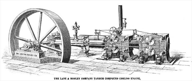 1890 Lane & Bodley, Tandem Compound Corliss Steam Engine
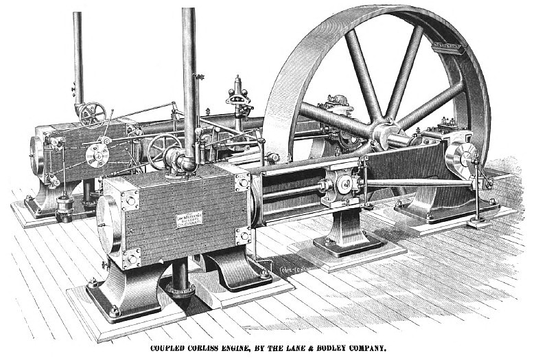 1890 Lane & Bodley, Coupled Compound Corliss Steam Engine
|
|