|
Title: |
1910 Image-John Steptoe & Co., Metal Shaper |
|
Source: |
Railway Master Mechanic Oct 1910 pg 464 |
|
Insert Date: |
3/14/2011 9:12:50 PM |
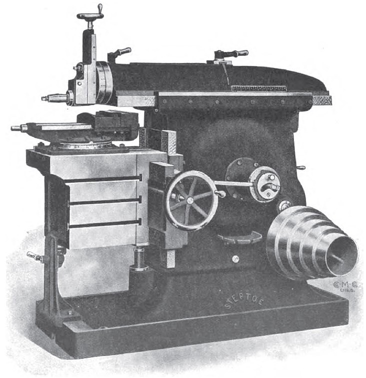
The John Steptoe .Shaper Co.. of Cincinnati, is the manufacturer of the heavy shapers which are familiar machines in every well equiped shop. The illustration herewith is that of a newly d«signed 24-in. back geared shaper, manufactured by this company. It is built especially for very heavy work, and the ram and cross rail bearings were therefore made exceptionally heavy. A new form of table support is used to avoid the possibility of any springing of the table while the cut is being taken. A roller in the table support rolls under a planed surface on the bottom of the table, out of the way of chips and dirt, with a minimum amount of friction while the table is moving. This table support is also directly under the cut, where it is most needed. The machine is of very simple design, and has nothing on it to get out of order. The back gear arrangement consists of a pair of sliding gears, and when one gear is working, the other is out of mesh. The only wear that occurs on these gears is when they are actually working. These gears are keyed to the shaft, and there are no idle gears running loose on shafts. There is no wear on the hole in the gears, which avoids the rattling that is very often heard in back geared shapers.
All shaft bearings in this machine are provided with cast iron bushings, which are pressed into place. The shaft bearings are also equiped with ring oilers, and spiral oil grooves are turned in the shafts to insure the oil being washed back and forth over the entire length of the bearing, thus keeping these bearings constantly flooded in oil, which prevents the possibility of their getting hot and cutting. The bull gear bearing in this machine is also provided with a chain oiler, a new feature in shaper construction. The column, ram and base have been very heavily ribbed and braced, and the column of the machine has been made exceptionally heavy on the operating side. The column has been made in the shape of a basin on the operating side, which adds rigidity to that part of the machine.
The back gears are shifted by means of a lever at the back of the column, and the machine can be operated as either a single geared or a back geared shaper. Two changes of speed are secured for each step of the cone-pulley, by the shifting of this lever, and the speed is increased or decreased and the power increased or decreased. The length of stroke is adjusted by means of the bar, which projects through the feed plate. This can be done while the machine is running. The position of the ram can be changed by means of the lever shown at the center of the ram. This operation can also be pel formed while the machine is in motion. The head can be very quickly swiveled to any angle by means of the lever immediately in back of the head, thus avoiding the necessity of the use of bolts. The elevating screw for the table is entirely enclosed, and is of telescopic construction; the telescopic screw being made of three metals, the nut being made of bronze, the sleeve screw being made of cast iron and the screw under the table being made of steel, thus producing a minimum amount of friction. A ball bearing is provided under the table, so that it can be very readily raised or lowered. The cross feed screw for the table and the feed screw for the harp are both provided With hand wheels, which have been found far more convenient to the operator than the ball crank, which was formerly used on the machine. The base of this machine has been made exceptionally heavy to eliminate the possibility of a vibration, which might become very serious at the tool. The vise is graduated at an angle, to enable the operator to read the graduations readily without stooping over. The upper jaw of the vise is held in position by means of slats, which grip firmly around the lower jaw. Two extra clamping bolts are provided or the top of the uper jaw, as the work has a tendency to crawl when being tightened in the vise. By tightening these bolts, the work is pulled firmly against the lower jaw, thereby insuring accuracy. This is found to be very necessary in tool room work. The holes in the feed plate are drilled in accordance with the teeth in the feed ratchet. The holes are reamed tapered, and the pin which fits into these holes is also tapered, so that any wear that may occur is taken up automatically. |
|
 1910 John Steptoe & Co., Metal Shaper
|
|