|
Title: |
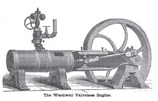
1884 Image-George J. Wardwell, Valveless Steam Engine |
|
Source: |
The Engineer's Handy Book 1884 pg 241 |
|
Insert Date: |
2/28/2011 12:36:18 PM |
The cut on page 241 represents Wardwell's Valveless Engine. As will be observed, it is a horizontal engine, with one end of a girder frame bolted to and supporting the cylinder, and the other supporting the pillow-block. The pillow-block brasses are provided with side adjustment wedges, operated from the top face of the cap by bolts and nuts. The cross-head has V-shaped bearings, top and bottom, with a wrist-pin providing journal-bearings for the fork end of the connecting-rod. The straps at these ends of the rod are provided with the ordinary gibs and keys. At the crank-pin end, however, the strap is secured to the rod by a bolt passing through the strap, the key merely serving to adjust the brasses. The piston passes a working fit through the cross-head, being secured at each end by jamb-nuts, by which arrangement any lateral play of the piston-rod in the cross-head is prevented; but at the same time the rod rotates in the latter. To the extreme end of the piston-rod, after it has passed through the cross-head, there is keyed fast a section of a bevel-wheel containing 5 teeth, which gears into another containing 4 teeth; this latter section being bolted fast to the inside of one of the fork-arms of the connecting-rod; the outside arm being selected as affording the best advantages for adjustment. When the connecting-rod is attached to the crank- and cross-head, and steam admitted to the cylinder, a semirotary movement takes place in regular order, and. as the stroke proceeds, the steam passages are so arranged that steam cau be admitted, cut off, and exhausted at any desired point of the stroke. It is obvious, however, that to accomplish this the piston-head in the cylinder must be extra long in proportion to the stroke.
The piston is solid, similar to a plunger, and is a neat working fit in the bore of the cylinder. The wear is provided for by the insertion at each end of the piston-head of ordinary spring packing-rings; and to take up wear and prevent leakage from one port to the other, a straight, longitudinal, spring packing-piece is placed between the steam passages in the piston-head, thus preventing the escape from one port to the other. The steam-port is in the centre of the cylinder, and on top. The steam passages in the piston-head commence near one end, and run along the circumferential surface, in a longitudinal but curved line, so that the passage will remain full open to the cylinder steam-port, notwithstanding the rotary motion of the piston. At such part of the stroke, however, at the point at which the steam is to be cut off, the steam passage turns at an angle, and runs round nearly one half the perimeter of the piston-head, so that the rotary motion of the piston during the remainder of the stroke is insufficient to permit any communication between the cylinder-port and piston passages. So soon as the piston-head steam passage turns the angle above noted, the longitudinal movement of the piston-head past the cylinder steam-port cuts off the supply of steam, and the remainder of the piston-stroke is performed by expansion. The circumferential direction of the passage above referred to serves another purpose than acting as a cut-off, in that it enables the same passage to be used to convey the steam to the cylinder exhaust-port. After the steam passage has taken the circumferential direction referred to, it continues longitudinally to the end of the piston-head; the steam passage, while isolated from the cylinder steam-port, comes into open communication with the cylinder exhaust-port, and that stroke of the engine is completed. For the return-stroke, a similarly arranged passage is provided in the piston-head, and hence the piston requires but two passages, each of which operates alternately, as induction and eduction passages.
There were three of this description of engines on exhibition at the Centennial Exposition, which attracted considerable attention, in consequence of the arrangement for admitting and exhausting steam being entirely different from anything heretofore employed. Such engines possess no practical value, their chief interest consists in the novelty of the arrangement. |
|
 1884 George J. Wardwell, Valveless Steam Engine
|
|